1

I'm looking for a Normally-Open optocoupler board for arduino. I need to control power of a device (DC 12v, 500mA). I tried to use TLP281 board, which works, except that it inverts the output: device is powered when there is no control signal (i.e., it is Normally-Closed).

For this reason, the TLP281 board is not useful in my project.

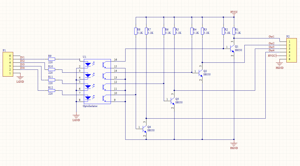
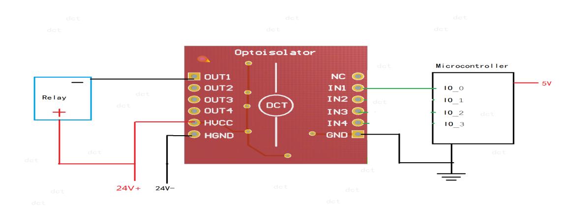
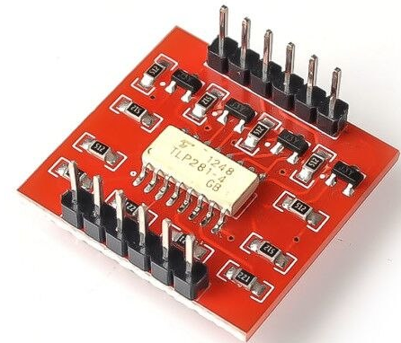
This is picture and schematics for TLP281 board:

enter image description here

enter image description here

enter image description here

I need an optoisolator board which works analogous to normally open mechanical relay: when there is no signal, device must not be powered; and when there is signal, device must be powered.

NOTE: workaround by inverting the control signal in microcontroller firmware is not permitted, as the device must not be powered when microcontroller is off

10
  • @JaromandaX Do you know a schematic which explains how to create Normally-Open relay based on TLP281 (or any other opto-isolator)? Commented Feb 27, 2019 at 3:06
  • 1
    @JaromandaX I tested it and I can say for sure that this board inverts the signal (on low input, there is power on output, on high input, there is no power on output). Commented Feb 27, 2019 at 5:32
  • I think every driver does what you want, only this one has it inverted. What is the device? A motor? Do you need pwm to control the speed? This could be a normal driver: aliexpress.com/store/product/… There are similar modules for 4 and 8 channels.
    – Jot
    Commented Feb 27, 2019 at 6:10
  • @Jot the device is Panasonic KX-TCD245, I need just to turn it on or off. Commented Feb 27, 2019 at 7:25
  • @JaromandaX the links that you give are for the same board which is in OP - it is Normally-Closed - I need Normally-Open Commented Feb 27, 2019 at 7:27

2 Answers 2

2

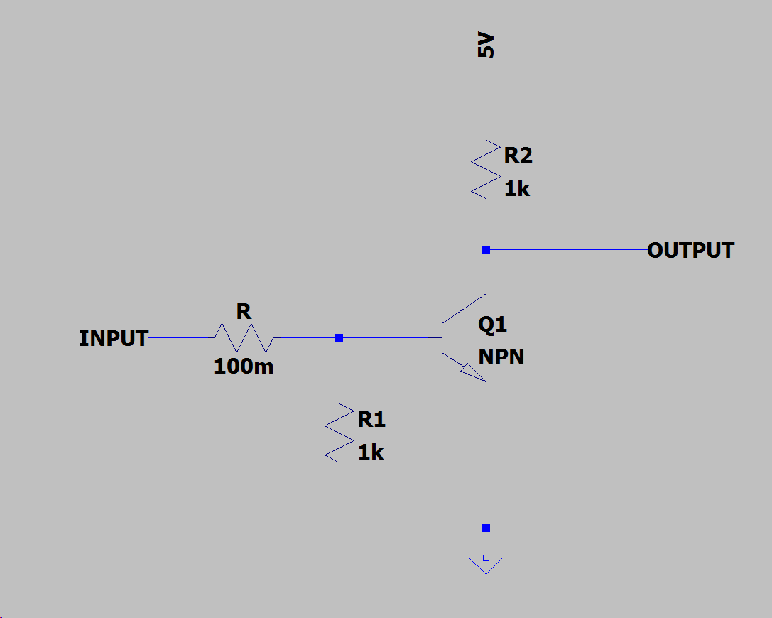
I don't think there is a need for a specific "normally-open" opto-coupler. Same result can be easily achieved by using "normally-closed" opto-coupler and making a slightly modified "NOT" logic gate using three resistors and NPN transistor.

NOT gate design

1. When INPUT is LOW:

Base of Q1 is shorted to ground through R1 so Q1 not letting the magic pixies go through. This makes OUTPUT show 5V and be in HIGH logic state.

2. When INPUT is HIGH:

Base of Q1 is powered by voltage divider R/R1. R needs to be much lower than R1 to keep Q1 saturated. This makes Q1 to be passing current and setting OUTPUT to LOW state by creating a voltage divider R2/Q1(collector-emitter resistance) This means that value of R2 should be much higher then c-e resistance of Q1.

3. When INPUT is floating (microcontroller is turned off):

Any voltage on INPUT caused by imperfections of the hardware, E-M noise induction, static electricity, etc. should be discharged to ground by resistors R+R1 keeping INPUT in LOW state. (This means that R+R1 cannot have to high value or the discharge speed might be to slow)

4
  • There is a problem with your solution: microcontroller is powered from USB, so the "5V" in your scheme will not be there when microcontroller is off. Thus, changes must be made to "output" side of optocoupler, not to "input" side. Commented Feb 28, 2019 at 3:32
  • If you use tougher npn transistor (for example the same one as uour opro-coupler) and higher resistor values (similar values as your opto-coupler) you can use this with 12V power source. You can remove R1 then because right side is never floating. Commented Feb 28, 2019 at 8:55
  • If I understand you correctly, you are suggesting something like this, right? ti.com/lit/ds/symlink/uln2003a.pdf Commented Mar 1, 2019 at 6:34
  • Actually I was suggesting that you simply get S8050 transistors (100 for 1 USD) and 5.1K resistors (100 for 0.70USD) and make a NOT gate with identical load bearing properties to the opto-coupler you shown. I assumed that you use that opto to steer a MOSFET since anything spiking above 500mA could burn it anyway (S8050 used in opto is rated for max 500mA) Commented Mar 1, 2019 at 8:32
1

For those, who are stumbling over this old thread and @igor-liferenko, since this board is still quite common:

This board definitely does NOT invert the inputs.

The comment of Igor Liferenko "tested it and I can say for sure that this board inverts the signal (on low input, there is power on output, on high input, there is no power on output)." is wrong. I don't know what he has tested, but both the schematics and tests show, that the board does not invert (or actually inverts twice -- once by the TLP281-4 itself and once by the following S8050-transistors).

So: low on input -> low on output; high on input -> high on output.

Your Answer

By clicking “Post Your Answer”, you agree to our terms of service and acknowledge you have read our privacy policy.

Not the answer you're looking for? Browse other questions tagged or ask your own question.