I have a 512 pulses encoder with four wires: +5V, ChannelA, ChannelB, GND and I'm using it as feedback for my motor position (max 80 RPM) on Arduino UNO. Everything works fine, but I need also to generate a +5V signal everytime ChannelA is HIGH since I need to use it to trigger further actions.
I was thinking to read ChannelA by using an optocoupler in order to split the signal and use it both for feedback and for the +5V signal. Is it possible?
Is there any other easier solution to do that?
EDIT: I try to explain better what the additional device must do.
The device is a video camera system that takes a +5V signal from the encoder to trigger some actions by software (create key frames or more) and we need it for our computer vision system. I just need to use the encoders both for the motor feedback and to trigger the video camera. The signal is always +5V so I do not have problems with voltage levels. What do you suggest? I do not have to drive loads from channelA output, I just need the +5V signal to trigger the video camera. Can I split the channelA output and use it both for the motor controller and the video camera inputs?
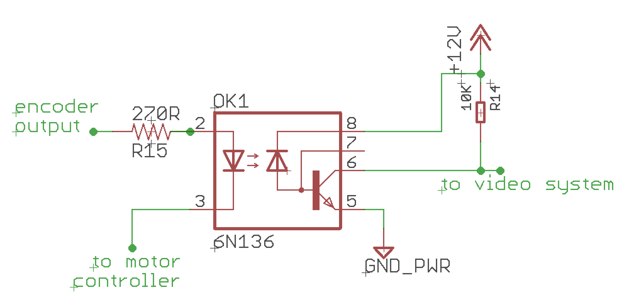
EDIT2: Following the useful suggestions of @st2000 I tried to think to a solution like this:
Do you think it can work?
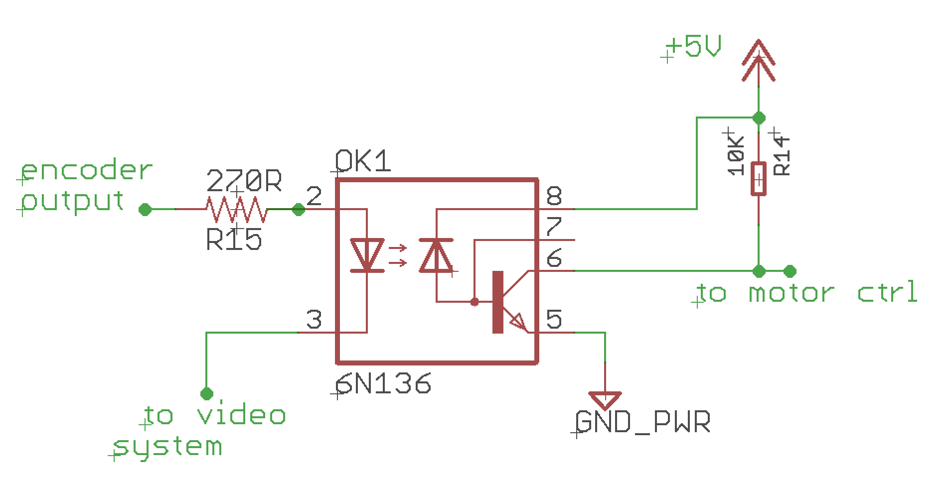
EDIT3: I changed swapped the motor controller and the video system positions in the circuit and I changed the voltage source from +12VDC to +5VDC for the motor controller since it accepts only +5V signals as input.
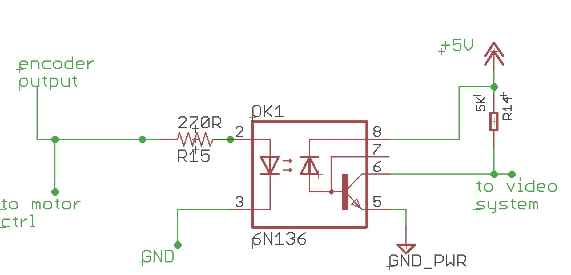
EDIT4: Following the suggestions of @st2000, I changed the circuit design by placing in parallel both devices (motor controller and video system) by using the optocoupler (6N136) only for the video output to isolate it from the whole system.


