added 42 characters in body
Source Link
Filip Franik
  • 1.3k
  • 1
  • 8
  • 22

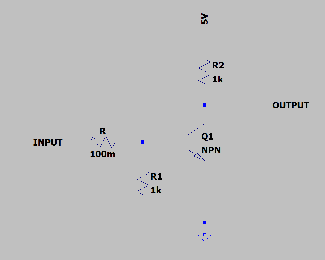
I don't think there is a need for a specific "normally-openopen" opto-coupler. Same result can be easily achieved by using "normally-closed" opto-coupler and making a slightly modified "NOT" logic gate using three resistors and NPN transistor.

NOT gate design

1. When INPUT is LOW:

Base of Q1 is shorted to ground through R1 so Q1 not letting the magic pixies go through. This makes OUTPUT show 5V and be in HIGH logic state.

2. When INPUT is HIGH:

Base of Q1 is powered by voltage divider R/R1. R needs to be much lower than R1 to keep Q1 saturated. This makes Q1 to be passing current and setting OUTPUT to LOW state by creating a voltage divider R2/Q1(collector-emitter resistance) This means that value of R2 should be much higher then c-e resistance of Q1.

3. When INPUT is floating (microcontroller is turned off):

Any voltage on INPUT caused by imperfections of the hardware, E-M noise induction, static electricity, etc. should be discharged to ground by resistors R+R1 keeping INPUT in LOW state. (This means that R+R1 cannot have to high value or the discharge speed might be to slow)

I don't think there is a need for a specific "normally-open opto-coupler. Same result can be easily achieved by making a slightly modified "NOT" logic gate using three resistors and NPN transistor.

NOT gate design

1. When INPUT is LOW:

Base of Q1 is shorted to ground through R1 so Q1 not letting the magic pixies go through. This makes OUTPUT show 5V and be in HIGH logic state.

2. When INPUT is HIGH:

Base of Q1 is powered by voltage divider R/R1. R needs to be much lower than R1 to keep Q1 saturated. This makes Q1 to be passing current and setting OUTPUT to LOW state by creating a voltage divider R2/Q1(collector-emitter resistance) This means that value of R2 should be much higher then c-e resistance of Q1.

3. When INPUT is floating (microcontroller is turned off):

Any voltage on INPUT caused by imperfections of the hardware, E-M noise induction, static electricity, etc. should be discharged to ground by resistors R+R1 keeping INPUT in LOW state. (This means that R+R1 cannot have to high value or the discharge speed might be to slow)

I don't think there is a need for a specific "normally-open" opto-coupler. Same result can be easily achieved by using "normally-closed" opto-coupler and making a slightly modified "NOT" logic gate using three resistors and NPN transistor.

NOT gate design

1. When INPUT is LOW:

Base of Q1 is shorted to ground through R1 so Q1 not letting the magic pixies go through. This makes OUTPUT show 5V and be in HIGH logic state.

2. When INPUT is HIGH:

Base of Q1 is powered by voltage divider R/R1. R needs to be much lower than R1 to keep Q1 saturated. This makes Q1 to be passing current and setting OUTPUT to LOW state by creating a voltage divider R2/Q1(collector-emitter resistance) This means that value of R2 should be much higher then c-e resistance of Q1.

3. When INPUT is floating (microcontroller is turned off):

Any voltage on INPUT caused by imperfections of the hardware, E-M noise induction, static electricity, etc. should be discharged to ground by resistors R+R1 keeping INPUT in LOW state. (This means that R+R1 cannot have to high value or the discharge speed might be to slow)

Source Link
Filip Franik
  • 1.3k
  • 1
  • 8
  • 22

I don't think there is a need for a specific "normally-open opto-coupler. Same result can be easily achieved by making a slightly modified "NOT" logic gate using three resistors and NPN transistor.

NOT gate design

1. When INPUT is LOW:

Base of Q1 is shorted to ground through R1 so Q1 not letting the magic pixies go through. This makes OUTPUT show 5V and be in HIGH logic state.

2. When INPUT is HIGH:

Base of Q1 is powered by voltage divider R/R1. R needs to be much lower than R1 to keep Q1 saturated. This makes Q1 to be passing current and setting OUTPUT to LOW state by creating a voltage divider R2/Q1(collector-emitter resistance) This means that value of R2 should be much higher then c-e resistance of Q1.

3. When INPUT is floating (microcontroller is turned off):

Any voltage on INPUT caused by imperfections of the hardware, E-M noise induction, static electricity, etc. should be discharged to ground by resistors R+R1 keeping INPUT in LOW state. (This means that R+R1 cannot have to high value or the discharge speed might be to slow)