1

I have a 512 pulses encoder with four wires: +5V, ChannelA, ChannelB, GND and I'm using it as feedback for my motor position (max 80 RPM) on Arduino UNO. Everything works fine, but I need also to generate a +5V signal everytime ChannelA is HIGH since I need to use it to trigger further actions.

I was thinking to read ChannelA by using an optocoupler in order to split the signal and use it both for feedback and for the +5V signal. Is it possible?

Is there any other easier solution to do that?

EDIT: I try to explain better what the additional device must do.

The device is a video camera system that takes a +5V signal from the encoder to trigger some actions by software (create key frames or more) and we need it for our computer vision system. I just need to use the encoders both for the motor feedback and to trigger the video camera. The signal is always +5V so I do not have problems with voltage levels. What do you suggest? I do not have to drive loads from channelA output, I just need the +5V signal to trigger the video camera. Can I split the channelA output and use it both for the motor controller and the video camera inputs?

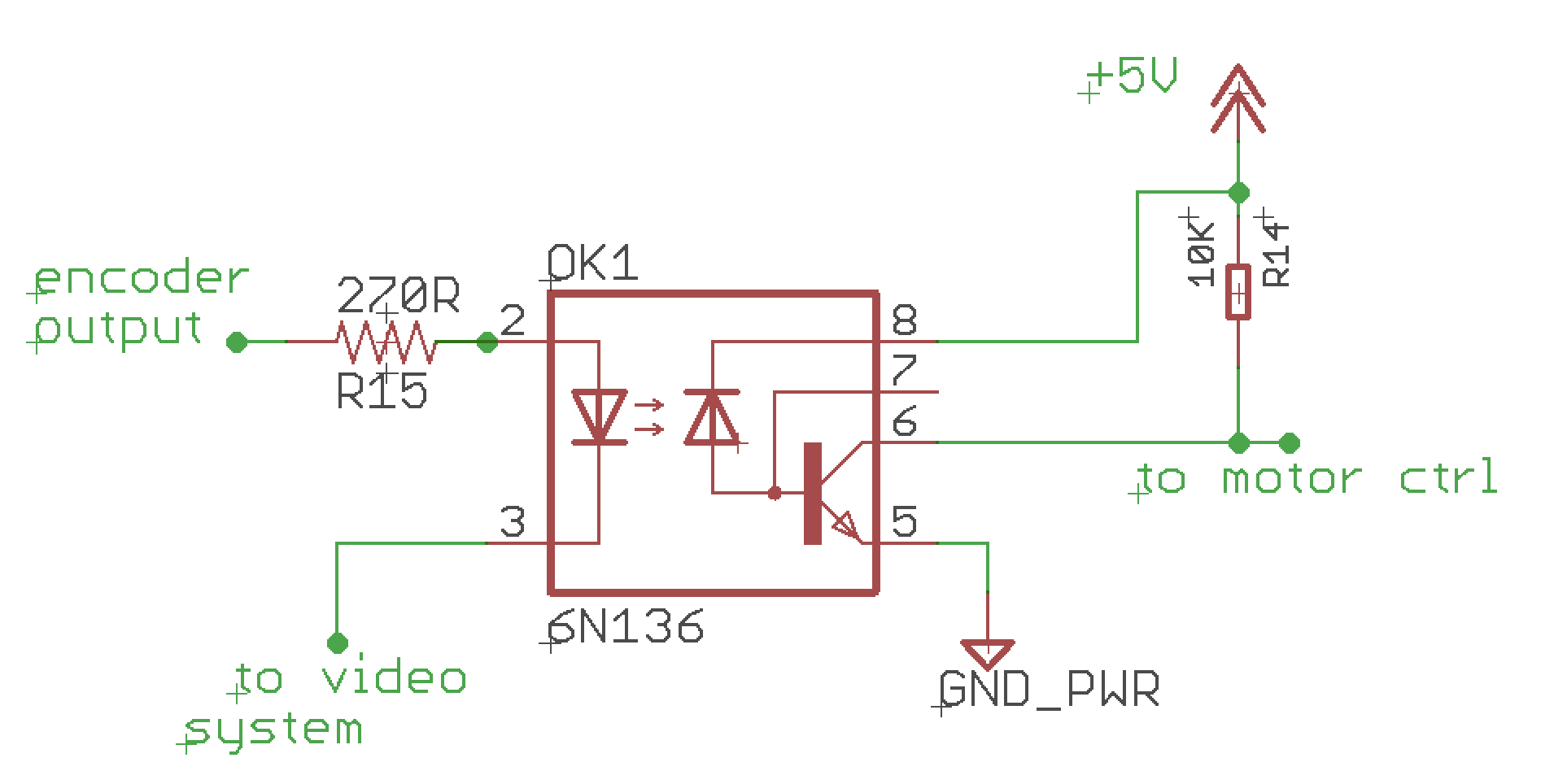
EDIT2: Following the useful suggestions of @st2000 I tried to think to a solution like this:

enter image description here

Do you think it can work?

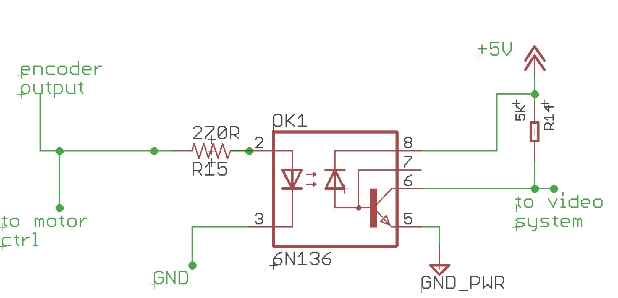
EDIT3: I changed swapped the motor controller and the video system positions in the circuit and I changed the voltage source from +12VDC to +5VDC for the motor controller since it accepts only +5V signals as input.

enter image description here

EDIT4: Following the suggestions of @st2000, I changed the circuit design by placing in parallel both devices (motor controller and video system) by using the optocoupler (6N136) only for the video output to isolate it from the whole system.

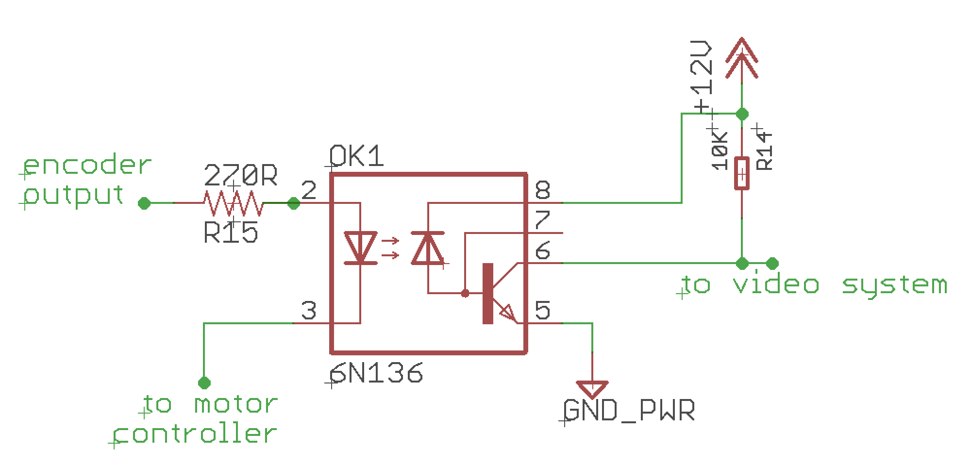
enter image description here

5
  • 1
    Possible, yes. But you may get it easier. For what do you need that 5V signal from channel A?
    – chrisl
    Commented Oct 16, 2020 at 7:13
  • 2
    Can't you just split the channelA encoder output, to go to both the Arduino and your other mystery device? Please tell us more about what it is you are trying to do, and what the actual problem is.
    – Gerben
    Commented Oct 16, 2020 at 12:02
  • 1
    Thank you for all your assistance! The mistery device is a video camera system that takes a +5V signal from the encoder to trigger some actions by software (create key frames or more) and we need it for our computer vision system. I just need to use the encoders both for the motor feedback and to trigger the video camera. The signal is always +5V so I do not have problems with voltage levels. What do you suggest? Commented Oct 17, 2020 at 8:09
  • A few things, people don't usually design circuits here, this site is designed to build a database of clear questions and concise answers. It needs to be searchable so questions are encouraged to be specific. For instance it would be better if you spread these questions out in individual posts. In general, if other people can not use your question and any ensuing answer, it is not a good fit for the many stackexchange sites.
    – st2000
    Commented Oct 24, 2020 at 14:40
  • That said, I would clean your post of unnecessary schematics leaving only the last one. We can work off that one. But keep in mind my answers are going to be general to keep within the guide lines of stackexchange sites and may not work for your particular case. In other words by no means should you assume we will create a working circuit. The intent is to suggest some methods used my some to help design a circuit.
    – st2000
    Commented Oct 24, 2020 at 14:45

2 Answers 2

1

A simple cheat is to place the LEDs of the two opto couplers in series and then modify the current limit resistor to bring the current back to where it should be.

1

People sometimes use optical couplers when anticipating large voltage differences or the potential for large voltage differences. This may always be the case as in a light dimmer. Or may preventative as in ground loop mitigation for MIDI connections. If you anticipate these types of situations then an optical coupler may be a good design choice.

Alternatively if the signal is changing between 0 volts and 5 volts and the fan out of the signal is larger then the existing load and the new load combined and the new load is 5 volt tolerant then the signal might be able to drive both loads.

You might seek out the specifications of the 3 connected devices in question. At the very least, discover the current the encoder output will support. Then measure the resistance to ground of the input to the motor controller and the resistance to ground of the input to the video equipment. Find the parallel resistance of these two resistance and calculate the current at 5 volts. If the current is substantially less then the specified capacity of the encoder, the encoder might be able to drive the 2 loads. This assumes many things such as no ground loops being present. There are so many variable it is difficult to be predict the outcome.

12
  • 1
    Thank you for making your question more complete. It is still a mystery what is inside the video equipment. It may be a high impedance device like a MOSFET with a load resistor to ground to mitigate noise problems. But that is just a guess. Also, your video equipment may be only inches away. Or may be across the lab. Logic level signals can be adversely affected by long wires. This is turning into a complex problem.
    – st2000
    Commented Oct 17, 2020 at 13:20
  • 1
    Hi @MarcusBarnet, we are getting into a situation where we can not assure success. It is at these point I start to consider what risks I am willing to take verses the effort to discover everything about everything involved. For example I would ask myself how much would a new encoder cost if the current one failed. Keep in mind you are asking this question in the Arduino forum where parts very rarely cost more then $50. That said, 1 meter isn't that long in a quiet environment. Did have a prof w/a pulsing ruby laser in a lab once. That didn't go well. Hi impedance isn't a bad thing ...
    – st2000
    Commented Oct 18, 2020 at 21:25
  • 1
    ... unless there's a lot of noise. Guessing, what I would do is to make sure there are no ground loops. That can blow out connected devices quickly. Make sure the input impedance to ground is high for both loads. Scope the output of the encoder w/no load. Scope it w/the motor controller only. Scope it w/the video equipment only. If both look good then connect them both and verify the signal from the encoder still looks good. If you are iffy about doing this, then I would suggest you find a tech or eng that is more familiar w/your setup who can do this for you.
    – st2000
    Commented Oct 18, 2020 at 21:35
  • 1
    It is likely the optical coupler will be fast enough. The challenge is using an optical coupler. You likely need a series resistance between the output of the encoder and the LED inside the optical coupler. Then, you likely need to arrange the output of the optical coupler similar to an open collector output and pull the output high through another resistor. Possibly something like this.
    – st2000
    Commented Oct 20, 2020 at 3:46
  • 1
    As this isn't a forum we'll eventually pass a threshold and the web site will ask us to move this discussion to a different page. Looking at the optical coupler specifications here I see where pin 3 is connected to ground. It is more likely the motor controller should be connected to the encoder output instead.
    – st2000
    Commented Oct 21, 2020 at 13:00

Your Answer

By clicking “Post Your Answer”, you agree to our terms of service and acknowledge you have read our privacy policy.

Not the answer you're looking for? Browse other questions tagged or ask your own question.