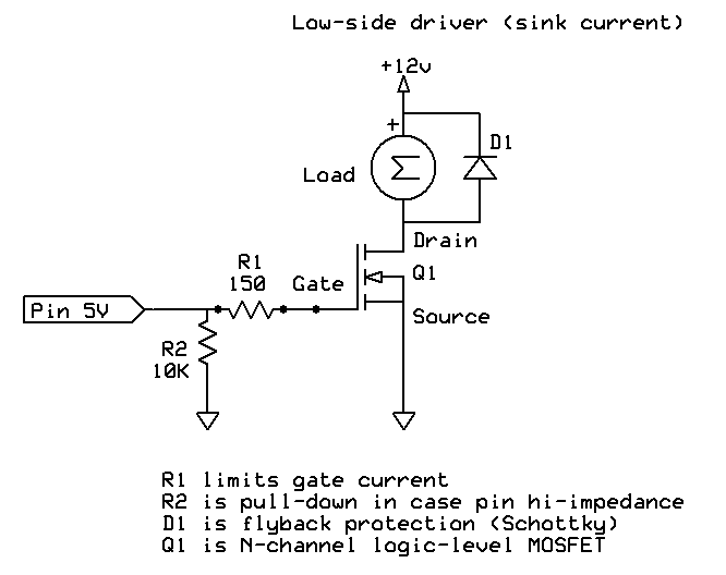
You would be better off using a MOSFET which, when on, has quite a low resistance. For example the RFP30N06LE datasheet shows a RDS(on) of 0.047 Ω at 30A and 5V.
Using Ohm's Law we therefore expect a voltage drop of:
V = IR
V = 0.5 x 0.047
V = 0.0235
Thus, only 23 mV drop if you are drawing half an amp. I measured using a toy that drew 200 mA and found a 5 mV drop at 1.5V (compared to the theoretical 9 mV).
I have a page about driving motors that illustrates how you might wire up such a device.

The 12V on that schematic could just as easily be 1.5V.
The diode on the schematic is a snubber diode which protects the transistor from flyback voltages from the motor.
Comparison to transistor
BJT transistors will have a higher voltage drop between collector and emitter. For example the 2N3904 has a 200 mV drop (0.2V) (called VCE(sat)) when conducting 50 mA. This is a somewhat larger drop than the 5 mV drop that I got with the MOSFET, and a somewhat larger percentage of the 1.5V that you are starting with.

