Maybe this is a question for Electronics SE but I’m not a member there yet so hopefully someone will have an answer here.
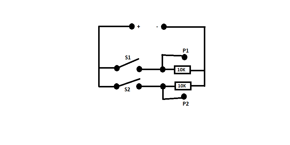
I did an experiment with having some push-to-make buttons connected to my Uno. I copied the circuit from the aduino.cc website and all worked exactly as expected. Here is my schematic of the circuit as I have it now:
 The pins are both held LOW by the Pulldown resistor until the switch is closed, when they go HIGH.
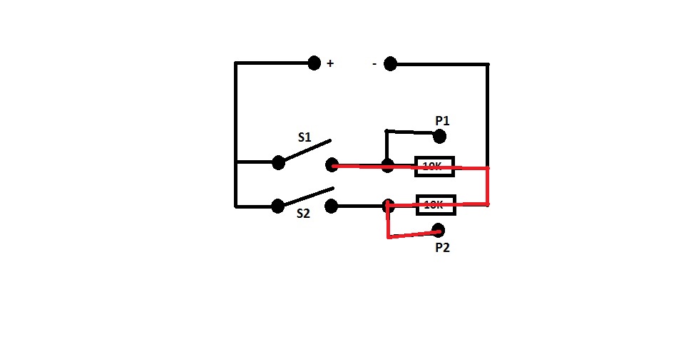
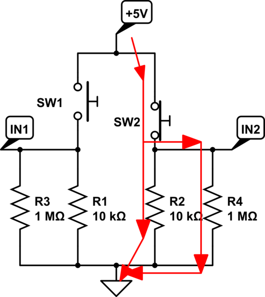
All well and good. But I’ve just been looking at the circuit and something puzzles me. I can see a direct connection from Switch 1 to Pin 2 VIA the resistors and the Ground connection – and vice versa, S2 to P1. See my pathway in Red here:
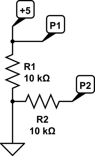
 Now, to be clear, this is NOT happening – but I just want to understand why not. Is it just that the 2 resistors in combination provide enough resistance to stop the opposite pin from going HIGH? In which case, this Pulldown resistor is actually serving 2 completely different functions in the circuit…?


