1

I am currently trying to generate a 38 KHz signal for my TSOP4838 (http://www.vishay.com/docs/82459/tsop48.pdf) with an ATtiny84A.

I know the real thing would be to utilize a timer but the ATtiny only has 2 Timers (T0 and T1). Timer1 can not be used because it is already used by other features.

I don't want to transmit actual data to the TSOP4838. I only want to use it as a light barrier (Iknow there are better ICs for that but I am stuck with the ones I already have).

So what I have tried so far is setting up timer0 for my PWM stuff and everything worked IR LED-wise. The delay functions (micros(), millis() etc.) stopped working and prevented me from using my serial communication. I tried to change the code in wiring.c to use a prescaler of 1 instead of 64 by changing the defines but that didn't work out.

I am now stuck with two options I guess:

A: somehow modify timer0 to generate my 38 KHz signal and still provide correct functionality for the timing functions.

B: let timer0 be initialized the way the Arduino wants it and utilize the delay functions to blink the IR LED.

I would prefer A but Google didn't give me a solution. Maybe some of the gurus around here could help?

If A is not possible can somebody give me a hint how to "bit bang" the IR LED with delay? (I guess that is a silly question but I can't figure it out at the moment :()

1
  • Sorry, but.... are you really using a microcontroller to generate a 38khz square wave and nothing more?
    – frarugi87
    Commented Nov 27, 2015 at 11:39

4 Answers 4

1

A 38kHz square wave at 50% duty cycle would be a transition running at 38x2=76kHz. That is 1/76,000 = 0.000013158s, or 13.158µs. That's quite a high accuracy to try and achieve with delays on a small chip like the 84A.

I assume you are running it at 8Mhz (internal calibrated RC oscillator) - that means each clock tick is 1/8000000=125ns long. so 13156ns would equate to 105.248 clock cycles. That can't happen, so the closest you would get is 105 clock cycles, which would be 13125ns, or 76.190kHz, or an end frequency of 38.095kHz. So fairly close.

So now you need to create a tight loop that is exactly 105 clock cycles long including the toggling of the IO pin and the comparisons and branches for the loop. For that you need to do some careful instruction cycle counting and work in assembly language. Page 268 of the data sheet details the clock cycles used for each instruction.

The simplest (though most long winded) loop would be an OUT or SBR (depending on port) instruction (1 clock) to set the IO pin HIGH, then 104 NOPs (1 clock each), then an OUT or CBR to set it LOW (1 clock), then 102 NOPs (1 clock each), then an RJMP to go back to the start (2 clocks). That is then a grand total of 210 clock cycles, or 1/(210*0.000000125) = 38.095kHz.

You could compress all the NOP instructions down into a tight loop themselves by setting a register to a pre-defined loop count value, decrement it each pass - repeat if it's not 0. That means even more careful instruction counting to get that loop to equal the 104 or 102 clock cycles needed for the precise timing.

However all that is pretty much academic, because the loop will keep being interrupted by your timer 0 interrupt and cause jitter in your output as the interrupt routine is being run instead of your IO pin driving loop.

If you don't need absolutely reliable timing anyway it might be easier (though far less accurate) to use the micros() function to find when 13µs have elapsed and do it all in C instead of assembly. You will still need high speed direct port access rather than using digitalWrite() since digitalWrite() adds way too much overhead to be able to do that kind of timing reliably. Something like:

uint32_t start = micros();
while(1) {
    if (micros() - start >= 13) {
        start = micros();
        PORTB ^= 1<<4; // toggle B4
    }
}

Note the use of while (1) there rather than relying on the loop() function repeating itself. There is quite a large overhead in using the auto-repeating of loop() that can be avoided by looping within it with a while (1) like that. Of course, anything else you want to happen repeatedly would have to be inside that while loop, and most likely would impact your output timing somewhat.

So a much better solution would be to use a timer, since that is what they are there for. But fidding with timers breaks things like millis() and delay(). So the answer to that is don't use millis() and delay(). Instead create your own timing functions that are controlled by your own interrupt that does the pin IO - instead of relying on a system provided tick you create your own. If your interrupt is firing every 13µs then add 13 to a global counter - that counter is then the number of microseconds that have passed. When that count exceeds 1000 you subtract 1000 (don't zero it) and add 1 to a millisecond counter. Now you have the equivalent to millis() in a global (remember to make it volatile) variable that you can use instead of millis().

2
  • Thanks for the detailed answer ! I am using amtel studio with a cire that i compiled myself and therefore i am already not using loop or setup methods like i a arduino environment. I guess i'll try again to get the timer to do what i want. The bad thing is that i need to alter the TinyDebugSerial Class too because it seems to use the arduino milli functions...
    – traffiq
    Commented Nov 27, 2015 at 11:12
  • I am using an arduino nano as frequence generator and it generated me a stable frequency with an error less than 0,1kHz. But the TSOP382 stops receiving after 200ms. I have disabled all interrupts and made the on and off sequence equal.
    – ego2dot0
    Commented Mar 1, 2021 at 11:10
1

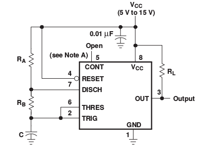
It would be much easier to use a dedicated IC such as a 555 or a 556. I built such a system based on these circuits IR Bream Break Detector

2
  • The R/C combination used there yields 41 kHz. Better suitable would be 22 nF / 860 Ω (38.054 kHz) or 47 nF / 400 Ω (38.297 kHz). Commented Dec 29, 2018 at 18:39
  • Edit: As two resistors are necessary for the astable version, use Ra = 1.2 kΩ, Rb = 12 kΩ and C = 1.5 nF, yielding 38.095 kHz. Ra/Rb/C see NE555 Data Sheet. Commented Dec 29, 2018 at 21:41
0

Several approaches are possible, some of which, but far from all, have been listed in previous answers. In following, I assume that by “use it as a light barrier” you mean that the TSOP4838 will be part of an object-intrusion detection system, rather than for transmitting data. As a consequence, some jitter and/or inaccuracy is acceptable. Note, all of the following methods assume that Arduino core code has set up timer 0 to support ordinary micros() and millis() calls.

Approach 1: Compute or calibrate a simple loop: In setup(), run a series of tests that find a value k to minimize error, via C code equivalent to the following Python:

for k in plausibleRange():
  err = genBurst19(k)
  if err < bestErr:
    bestErr = err
    bestK = k

where genBurst19() is like the following:

def genBurst19(k):
  t1=micros()
  for i in range(38):
    setPortBit(i&1)
    for j in range(k):
      nop
  t2=micros()
  return abs(t2-t1-500)

In other words, genBurst19() sends a burst of 19 cycles, which at 38 KHz should take 500 microseconds. It returns a measure of error to the caller.

After finding bestK, you can subsequently use it as a limit for other delay loops, or could just use repeated calls to genBurst19(bestK) whenever you want to generate some "38KHz".

Note, you might wish to try some minor variations, such as adding a second or third nop in the inner delay loop, or generating some higher multiple of 19 cycles. While a delay loop containing a single nop (or no nop at all, just an empty loop) has finer resolution than a loop with multiple nops, it may happen (depending on loop code) that a smaller error occurs with more. [But also see Approach 3 regarding fine tuning.]

Summary: This method is easy to use, has low jitter, but is limited in the accuracy it can attain.

Approach 2: Use a method analogous to Bresenham's to produce a signal with high-accuracy period, on the average, but with more jitter than Approach 1. Bresenham's algorithm tries to draw a straight line, on an x-y grid of pixels; you are trying to draw a straight line, on a time-vs-cycles grid.

In this method, you keep track of how many microseconds total should have elapsed, and when you fall too far behind, issue a delay with k-1 instead of k, to catch up; or if too far ahead, with k+1, to drop back. See my answer to stackoverflow 8113883 for a little more re Bresenham's method, in the line drawing context.

Summary: By applying Bresenham's method, you can get the average frequency as close as you like (when averaged over a few milliseconds).

Approach 3: This is more of a fillip than a whole approach. It modifies Approach 1 by adding the following C code before the for j in range(k): nop loop. It also needs a second parameter, l.

switch (l) {
  case 9: nop;
  case 8: nop;
  case 7: nop;
  case 6: nop;
  case 5: nop;
  case 4: nop;
  case 3: nop;
  case 2: nop;
  case 1: nop;
  case 0: ;
}

To use this approach, first find the best k using a series of calls like err = genBurst19(k,5). Then find the best l via err = genBurst19(bestK,l) for l from 0 to 9. [Note, a number smaller than 9 can be used in the above, if the for j in range(k): nop loop uses fewer cycles.]

Summary: This fillip can tune genBurst19() closer to single-nop accuracy.

0

I just built an NE555 based circuit for 38 kHz. Sender is a 950 nm IR diode, receiver is said TSOP4838. According to the NE555 Data Sheet, the frequency in astable mode is approximately

f ≈ 1.44 / (C (RA + 2 RB) )

NE555 astable circuit

Using values of RA = 1.8 kΩ, RB = 18 kΩ, C = 1 nF, the NE555 should generate a frequency of 38.095 kHz. Using these values, my circuit generated 34 kHz with some small changes of a few 100 Hz when using different resistors/capacitors (due to tolerance), but it came nowhere close to 38 kHz. This is probably because the frequency formula is an approximation. The easiest fix is probably to put a variable capacitor in parallel to C and use it for fine tuning, or a variable resistor to RB.

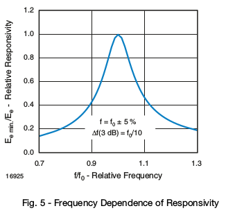
This may not be necessary in every case as the TSOP48xx uses a band pass filter, and 34 kHz are still recognized, only at lower responsivity. Note that this IR receiver (as well as others) have some limitations on pulse length, so you cannot constantly send 38 kHz but only for up to 70/f, which is around 1.8 ms. After that, the TSOP output switches off again, probably because the internal threshold is raised.

TSOP48 frequency dependency graph

Measurements

Some measurements from a logic analyzer (PulseView). This is from the above NE555 circuit which should yield 38 kHz.

Logic analyzer screenshot

I used an AND IC (74HCT08) to modulate a signal, generated by an Arduino, on top of the 38 kHz carrier. Sampling rate is 12 MHz. The probes measure:

  • D0: TSOP4838 output signal
  • D1: IR signal (carrier AND signal)
  • D2: Arduino signal
  • D3: 38 kHz carrier from NE555

38 kHz modulated IR signal

Your Answer

By clicking “Post Your Answer”, you agree to our terms of service and acknowledge you have read our privacy policy.

Not the answer you're looking for? Browse other questions tagged or ask your own question.