SN74HCT08 datasheet link
Source Link

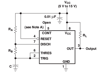
I just built an NE555 based circuit for 38 kHz. Sender is a 950 nm IR diode, receiver is said TSOP4838. According to the NE555 Data Sheet, the frequency in astable mode is approximately

f ≈ 1.44 / (C (RA + 2 RB) )

NE555 astable circuit

Using values of RA = 1.8 kΩ, RB = 18 kΩ, C = 1 nF, the NE555 should generate a frequency of 38.095 kHz. Using these values, my circuit generated 34 kHz with some small changes of a few 100 Hz when using different resistors/capacitors (due to tolerance), but it came nowhere close to 38 kHz. This is probably because the frequency formula is an approximation. The easiest fix is probably to put a variable capacitor in parallel to C and use it for fine tuning, or a variable resistor to RB.

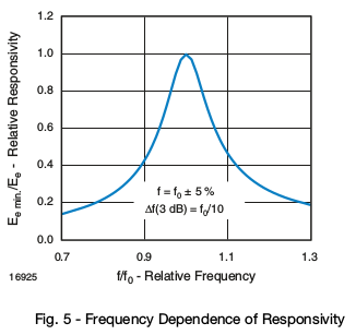
This may not be necessary in every case as the TSOP48xx uses a band pass filter, and 34 kHz are still recognized, only at lower responsivity. Note that this IR receiver (as well as others) have some limitations on pulse length, so you cannot constantly send 38 kHz but only for up to 70/f, which is around 1.8 ms. After that, the TSOP output switches off again, probably because the internal threshold is raised.

TSOP48 frequency dependency graph

Measurements

Some measurements from a logic analyzer (PulseView). This is from the above NE555 circuit which should yield 38 kHz.

Logic analyzer screenshot

I used an AND IC (74HCT0474HCT08) to modulate a signal, generated by an Arduino, on top of the 38 kHz carrier. Sampling rate is 12 MHz. The probes measure:

  • D0: TSOP4838 output signal
  • D1: IR signal (carrier AND signal)
  • D2: Arduino signal
  • D3: 38 kHz carrier from NE555

38 kHz modulated IR signal

I just built an NE555 based circuit for 38 kHz. Sender is a 950 nm IR diode, receiver is said TSOP4838. According to the NE555 Data Sheet, the frequency in astable mode is approximately

f ≈ 1.44 / (C (RA + 2 RB) )

NE555 astable circuit

Using values of RA = 1.8 kΩ, RB = 18 kΩ, C = 1 nF, the NE555 should generate a frequency of 38.095 kHz. Using these values, my circuit generated 34 kHz with some small changes of a few 100 Hz when using different resistors/capacitors (due to tolerance), but it came nowhere close to 38 kHz. This is probably because the frequency formula is an approximation. The easiest fix is probably to put a variable capacitor in parallel to C and use it for fine tuning, or a variable resistor to RB.

This may not be necessary in every case as the TSOP48xx uses a band pass filter, and 34 kHz are still recognized, only at lower responsivity. Note that this IR receiver (as well as others) have some limitations on pulse length, so you cannot constantly send 38 kHz but only for up to 70/f, which is around 1.8 ms. After that, the TSOP output switches off again, probably because the internal threshold is raised.

TSOP48 frequency dependency graph

Measurements

Some measurements from a logic analyzer (PulseView). This is from the above NE555 circuit which should yield 38 kHz.

Logic analyzer screenshot

I used an AND IC (74HCT04) to modulate a signal, generated by an Arduino, on top of the 38 kHz carrier. Sampling rate is 12 MHz. The probes measure:

  • D0: TSOP4838 output signal
  • D1: IR signal (carrier AND signal)
  • D2: Arduino signal
  • D3: 38 kHz carrier from NE555

38 kHz modulated IR signal

I just built an NE555 based circuit for 38 kHz. Sender is a 950 nm IR diode, receiver is said TSOP4838. According to the NE555 Data Sheet, the frequency in astable mode is approximately

f ≈ 1.44 / (C (RA + 2 RB) )

NE555 astable circuit

Using values of RA = 1.8 kΩ, RB = 18 kΩ, C = 1 nF, the NE555 should generate a frequency of 38.095 kHz. Using these values, my circuit generated 34 kHz with some small changes of a few 100 Hz when using different resistors/capacitors (due to tolerance), but it came nowhere close to 38 kHz. This is probably because the frequency formula is an approximation. The easiest fix is probably to put a variable capacitor in parallel to C and use it for fine tuning, or a variable resistor to RB.

This may not be necessary in every case as the TSOP48xx uses a band pass filter, and 34 kHz are still recognized, only at lower responsivity. Note that this IR receiver (as well as others) have some limitations on pulse length, so you cannot constantly send 38 kHz but only for up to 70/f, which is around 1.8 ms. After that, the TSOP output switches off again, probably because the internal threshold is raised.

TSOP48 frequency dependency graph

Measurements

Some measurements from a logic analyzer (PulseView). This is from the above NE555 circuit which should yield 38 kHz.

Logic analyzer screenshot

I used an AND IC (74HCT08) to modulate a signal, generated by an Arduino, on top of the 38 kHz carrier. Sampling rate is 12 MHz. The probes measure:

  • D0: TSOP4838 output signal
  • D1: IR signal (carrier AND signal)
  • D2: Arduino signal
  • D3: 38 kHz carrier from NE555

38 kHz modulated IR signal

added 41 characters in body
Source Link

I just built an NE555 based circuit for 38 kHz. Sender is a 950 nm IR diode, receiver is said TSOP4838. According to the NE555 Data Sheet, the frequency in astable mode is approximately

f ≈ 1.44 / (C (RA + 2 RB) )

NE555 astable circuit

Using values of RA = 1.8 kΩ, RB = 18 kΩ, C = 1 nF, the NE555 should generate a frequency of 38.095 kHz. Using these values, my circuit generated 34 kHz with some small changes of a few 100 Hz when using different resistors/capacitors (due to tolerance), but it came nowhere close to 38 kHz. This is probably because the frequency formula is an approximation. The easiest fix is probably to put a variable capacitor in parallel to C and use it for fine tuning, or a variable resistor to RB.

This may not be necessary in every case as the TSOP48xx uses a band pass filter, and 34 kHz are still recognized, only at lower responsivity. Note that this IR receiver (as well as others) have some limitations on pulse length, so you cannot constantly send 38 kHz but only for up to 70/f, which is around 1.8 ms. After that, the TSOP output switches off again, probably because the internal threshold is raised.

TSOP48 frequency dependency graph

Measurements

Some measurements from a logic analyzer (PulseView). This is from the above NE555 circuit which should yield 38 kHz.

Logic analyzer screenshot

I used an AND IC (74HCT04) to modulate a signal, generated by an Arduino, on top of the 38 kHz carrier. Sampling rate is 12 MHz. The probes measure:

  • D0: TSOP4838 output signal
  • D1: IR signal (carrier AND signal)
  • D2: Arduino signal
  • D3: 38 kHz carrier from NE555

38 kHz modulated IR signal

I just built an NE555 based circuit for 38 kHz. Sender is a 950 nm IR diode, receiver is said TSOP4838. According to the NE555 Data Sheet, the frequency in astable mode is approximately

f ≈ 1.44 / (C (RA + 2 RB) )

NE555 astable circuit

Using values of RA = 1.8 kΩ, RB = 18 kΩ, C = 1 nF, the NE555 should generate a frequency of 38.095 kHz. Using these values, my circuit generated 34 kHz with some small changes of a few 100 Hz when using different resistors/capacitors (due to tolerance), but it came nowhere close to 38 kHz. This is probably because the frequency formula is an approximation. The easiest fix is probably to put a variable capacitor in parallel to C and use it for fine tuning.

This may not be necessary in every case as the TSOP48xx uses a band pass filter, and 34 kHz are still recognized, only at lower responsivity. Note that this IR receiver (as well as others) have some limitations on pulse length, so you cannot constantly send 38 kHz but only for up to 70/f, which is around 1.8 ms. After that, the TSOP output switches off again, probably because the internal threshold is raised.

TSOP48 frequency dependency graph

Measurements

Some measurements from a logic analyzer (PulseView). This is from the above NE555 circuit which should yield 38 kHz.

Logic analyzer screenshot

I used an AND IC (74HCT04) to modulate a signal, generated by an Arduino, on top of the 38 kHz carrier. Sampling rate is 12 MHz. The probes measure:

  • D0: TSOP4838 output signal
  • D1: IR signal (carrier AND signal)
  • D2: Arduino signal
  • D3: 38 kHz carrier from NE555

38 kHz modulated IR signal

I just built an NE555 based circuit for 38 kHz. Sender is a 950 nm IR diode, receiver is said TSOP4838. According to the NE555 Data Sheet, the frequency in astable mode is approximately

f ≈ 1.44 / (C (RA + 2 RB) )

NE555 astable circuit

Using values of RA = 1.8 kΩ, RB = 18 kΩ, C = 1 nF, the NE555 should generate a frequency of 38.095 kHz. Using these values, my circuit generated 34 kHz with some small changes of a few 100 Hz when using different resistors/capacitors (due to tolerance), but it came nowhere close to 38 kHz. This is probably because the frequency formula is an approximation. The easiest fix is probably to put a variable capacitor in parallel to C and use it for fine tuning, or a variable resistor to RB.

This may not be necessary in every case as the TSOP48xx uses a band pass filter, and 34 kHz are still recognized, only at lower responsivity. Note that this IR receiver (as well as others) have some limitations on pulse length, so you cannot constantly send 38 kHz but only for up to 70/f, which is around 1.8 ms. After that, the TSOP output switches off again, probably because the internal threshold is raised.

TSOP48 frequency dependency graph

Measurements

Some measurements from a logic analyzer (PulseView). This is from the above NE555 circuit which should yield 38 kHz.

Logic analyzer screenshot

I used an AND IC (74HCT04) to modulate a signal, generated by an Arduino, on top of the 38 kHz carrier. Sampling rate is 12 MHz. The probes measure:

  • D0: TSOP4838 output signal
  • D1: IR signal (carrier AND signal)
  • D2: Arduino signal
  • D3: 38 kHz carrier from NE555

38 kHz modulated IR signal

Source Link

I just built an NE555 based circuit for 38 kHz. Sender is a 950 nm IR diode, receiver is said TSOP4838. According to the NE555 Data Sheet, the frequency in astable mode is approximately

f ≈ 1.44 / (C (RA + 2 RB) )

NE555 astable circuit

Using values of RA = 1.8 kΩ, RB = 18 kΩ, C = 1 nF, the NE555 should generate a frequency of 38.095 kHz. Using these values, my circuit generated 34 kHz with some small changes of a few 100 Hz when using different resistors/capacitors (due to tolerance), but it came nowhere close to 38 kHz. This is probably because the frequency formula is an approximation. The easiest fix is probably to put a variable capacitor in parallel to C and use it for fine tuning.

This may not be necessary in every case as the TSOP48xx uses a band pass filter, and 34 kHz are still recognized, only at lower responsivity. Note that this IR receiver (as well as others) have some limitations on pulse length, so you cannot constantly send 38 kHz but only for up to 70/f, which is around 1.8 ms. After that, the TSOP output switches off again, probably because the internal threshold is raised.

TSOP48 frequency dependency graph

Measurements

Some measurements from a logic analyzer (PulseView). This is from the above NE555 circuit which should yield 38 kHz.

Logic analyzer screenshot

I used an AND IC (74HCT04) to modulate a signal, generated by an Arduino, on top of the 38 kHz carrier. Sampling rate is 12 MHz. The probes measure:

  • D0: TSOP4838 output signal
  • D1: IR signal (carrier AND signal)
  • D2: Arduino signal
  • D3: 38 kHz carrier from NE555

38 kHz modulated IR signal