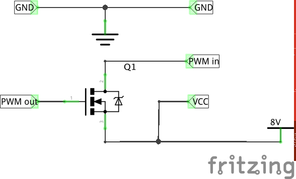
I have a control module that accepts 8V PWM signals. My goal is to send a 500Hz PWM signal from an Arduino to an 8V PWM input on the control module. Looks like everything generated from the Arduino is 5V. Is there a way to generate an 8V PWM output or method of manipulating that signal to reach 8V?
1 Answer
I'd suggest you use a power-source that delivers you 8V. Your Arduino takes anything from 7-12V to power it and it regulates it down to 5V. But you still can access the 8V from the RAW pins. Use a MOSFET like D1703L to control the 8V with an 5V Arduino digital pin.
You just connect Drain (D) to GND and Source (S) to your RAW 8V (don't forget to put your device between the Source and RAW 8V). Your Arduino digital pin goes to Gate (G), but to not draw to much current from the pin you might want to use a resistor of roughly 1kΩ.
This is the safest way that also allows for much higher voltage and also current for up to a few amps.
EDIT
You should not connect the PWM pin to Ground on your Arduino. But you have to connect both grounds together. I'm not sure where your 8V comes from so I made a sketch where the 8V is an external source and powers your device along with the MOSFET.
-
3Mosfets don't draw current from the gate, the resistor isn't strictly needed. Depending on the application, You might want to add a pull-down resisor on the output.– GerbenCommented Jul 29, 2016 at 13:46
-
I have attempted the circuit as suggested above with an N-channel MOSFET. This isn't working and I think my circuit is wrong. I can't use the MOSFET to switch ground, I need it to switch the 8V. So, here is how I connected the MOSFET: Gate to the Arduino output (with a 10k resistor to ground). Source to +8Vdc. Drain to the PWM input pin on the Electronic Control Module (8V PWM input). I have a feeling that because I'm switching the 8V through the transistor instead of ground, do I need to use a P-channel MOSFET?– ClintonCommented Aug 9, 2016 at 15:49
-
No, an N-Channel MOSFET is perfectly fine. Using a P-Channel would reverse the signal (Pin High -> switched off and vice versa). The MOSFET acts like a switch. It does not matter from which side you connect it as long you watch the polarity. Can you give a sketch of your circuit?– KwasmichCommented Aug 9, 2016 at 16:03
-
I have added a circuit sketch to the original question. Doesn't seem like I'm able to add an image to a reply. Ok, thanks - I understand about the P & N channel now. Most of the circuit sketches I look at (from Google and such) are switching ground through the transistor. Does it even work the way I'm trying to do it, or do I need to configure this circuit differently?– ClintonCommented Aug 9, 2016 at 16:16
-


