My question is similar to this one: Motor shield and wireless transceiver compete for same pins But not exactly the same!
I would like to know if the solution is as practical, though.
I have an Arduino Mega 2560 R3, with an Arduino Motor shield plugged into it. Now I want to use the Adafruit CC3000 WiFi shield. It plugs in fine, but when reading the specifications, it wants to use pins 13, 12, 11 which are also used by the Motor shield. I also want to use pin 10 as a servo is plugged into it. This is all on a robot so I don't have space to wire the shield separately through a breadboard or similar.
It should perhaps also be noted that I have the motor shield on top of the wifi shield so that the wifi shield can use the ICSP ports which the motor shield doesn't have, therefore any redirecting of pins on the CC3000 will mean that the motor shield pins will also be affected unless I redirect them too, and at that point I feel like it would be all a bit of a mess.
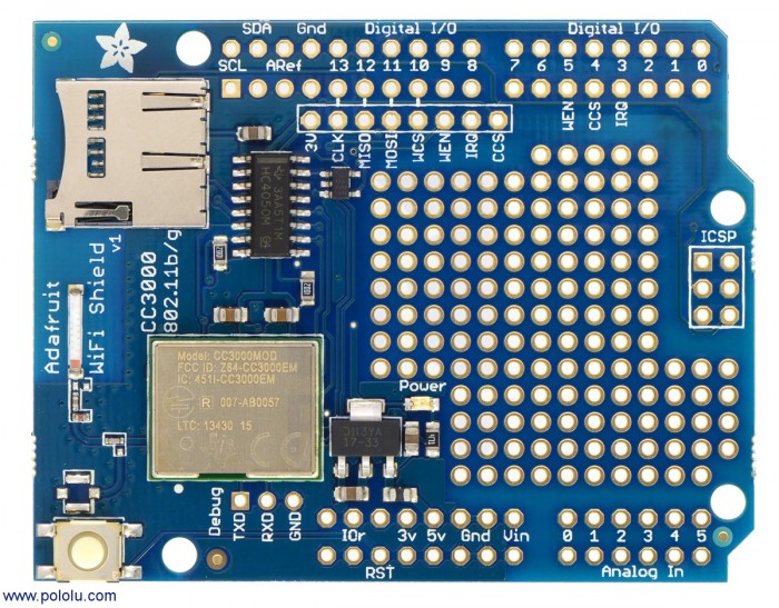
The solution to the other question was indeed to redirect the relevant pins to other free pins on the micro-controller board. However, I noticed that the Adafruit shield has a second row of connector holes next to the main pin holes. In the shield documentation I found, I didn't find any specific reference to these parts and in what situations they could be used, but maybe this is one of them.
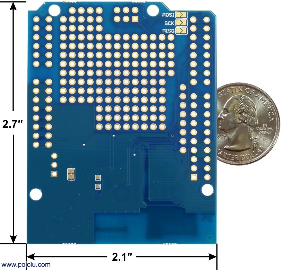
My concern with using these is that (as you can see in the second image below, ignoring the coin!), the ports are wired together in the board. Does this mean that it won't make any difference which I use; if I connect a second row of pins/connectors to these points will it simply transmit the same data down both sides? I don't know enough about how electronics work at that level to understand the consequences.
So really my question is: can I use the outside row of ports for my motor shield and the inside row for the wifi shield?
EDIT:
So I've spent until now on the Adafruit forums trying to get some help with this and I still am not all the way there... maybe at this point someone here can cast fresh eyes over my problem.
The Adafruit CC3000 uses both the dedicated ICSP pins and pins 3, 11-13 to transmit the same data. The reason for this is to do with compatibility between different Arduino boards and their versions. E.g. apparently the Uno uses those pins whilst the mega uses some of the pins in the 50s range. I'm not sure what to make of this as the Uno and most of the boards seem to have the ICSP pins, so if they're not used for this purpose then what's the point of connecting to them? Anyway.
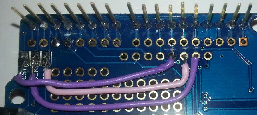
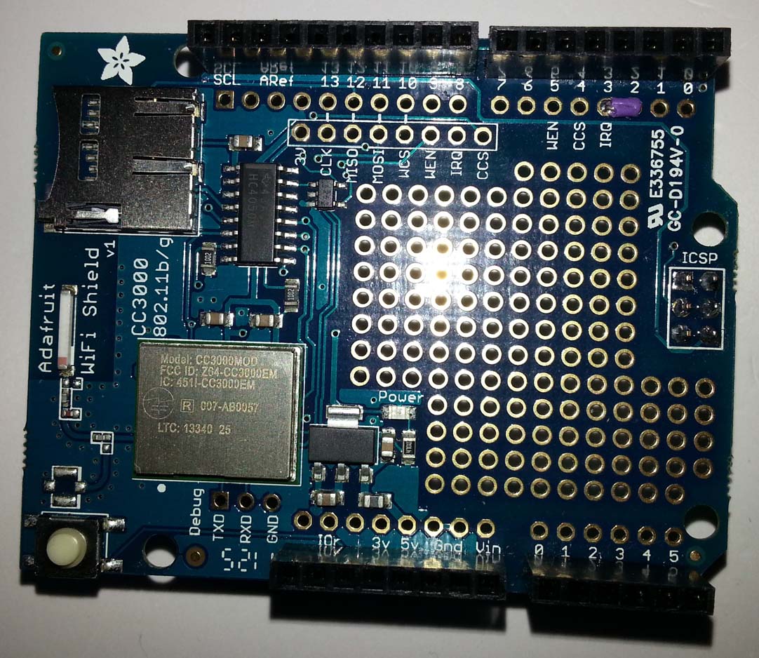
As it was explained to me, even if the board can use the ICSP pins to communicate with the microcontroller, it is still sending data via the other pins. So the main pins are essentially useless at this point. To make them useful again, the idea is that you sever the wires that are sending the data through them (often referred to as trace wires). This means that only the ISCP ones will be active for what they are needed, and the main pins will be free for other uses. This is what I ended up doing to my board for pins 11-13, and then for pin 3 I cut the trace wire and wired up the connection to pin 2 as these can both be used for an IRQ (interrupt request) on the Mega and I need pin 3 for the motor shield. The lighting on these pictures isn't the best, but you can see what I've done (the lower part of the second image shows where I made the cuts and the top image shows the wire connection):
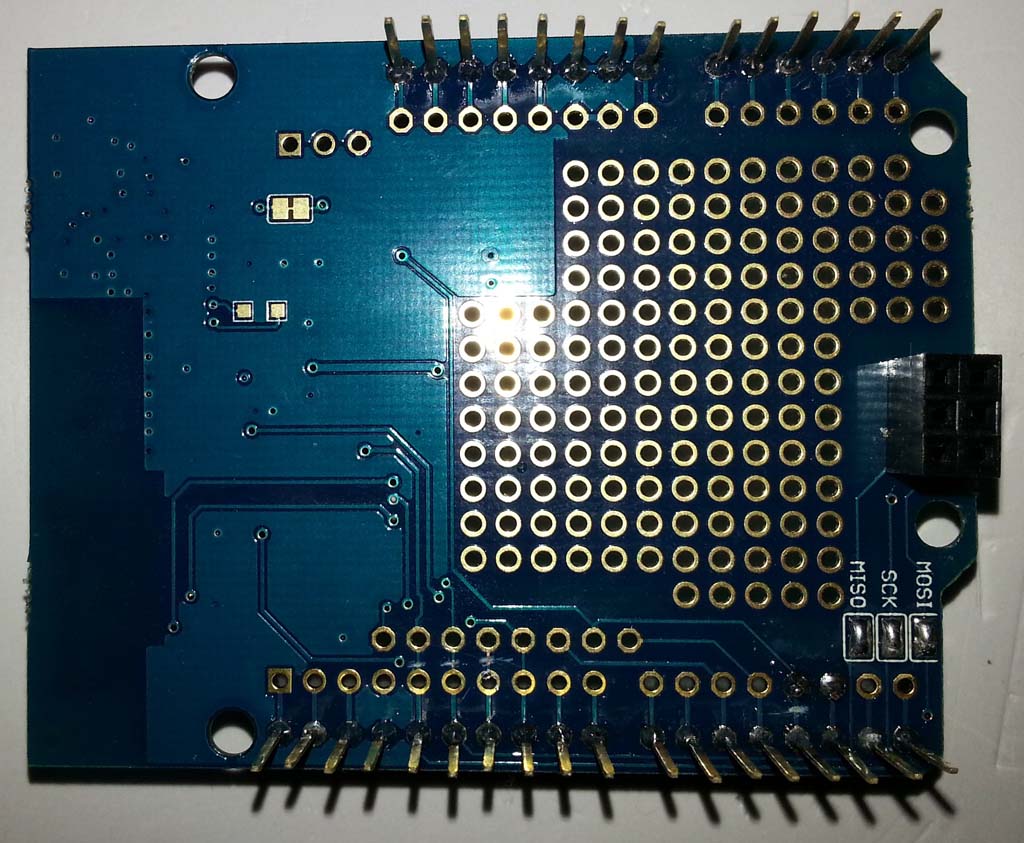
After doing that I have been testing the shield connected to both my Mega and my Uno and they both produce the same results. This is using the Adafruit-created library called Adafruit_CC3000_Library. It starts the initialisation, then whilst it's trying to run the code it gets stuck. I traced the problem to a while(1) loop of which you can only exit by meeting a condition which is never met in my case: if (*pucReceivedData == HCI_TYPE_EVNT). This may be because pucReceivedData is not initialised properly, but I don't know why and whether it has to do with my modifications. This happens in the hci_event_handler method of evnt_handler.cpp. This is through the main file and wlan.cpp so I won't write it here as it is simple enough to follow.
It should also be noted that this shield doesn't work properly with the later versions of the arduino IDE (1.5+) so I had to reinstall 1.0.6. To be honest, I got the same problem on both versions so who knows.
I realise that this is a very specific problem, but I figure that this may leave someone with a lot fewer issues in the future. If anyone has any bright ideas, even if just for testing then I would be grateful.

