1

I am trying to locate a schematic for the Adafruit motor shield v2.3. It has many ports and currently I have found little to no explanation of what is on the board. I located this picture which highlights the motor ports, servo ports, and Arduino Pins. But what about everything else?

What are the pin holes above and below the Arduino pins? Are they secondary positions for the pins? What is the PWMs 0,1,14,15? How is the big empty board in the center setup?

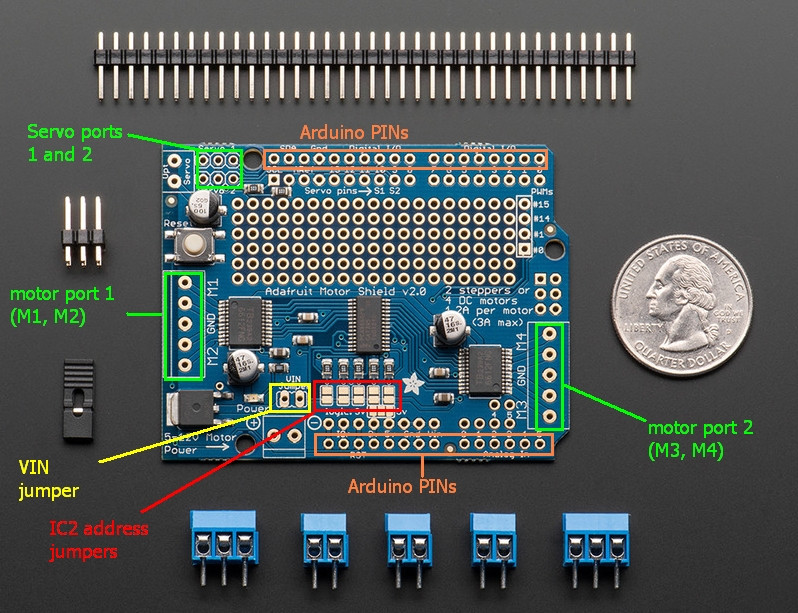
enter image description here

1 Answer 1

5

Everything can be found out by reading the schematic which, incidentally, is the first hit on Google when you search for "Adafruit motor shield 2.3 schematic":

enter image description here

What are the pin holes above and below the Arduino pins? Are they secondary positions for the pins?

Yes. They're just there to make it easy to solder wires and jumpers to.

What is the PWMs 0,1,14,15?

They are connected to PWM pins 0, 1, 14 and 15 of the PCA9685.

How is the big empty board in the center setup?
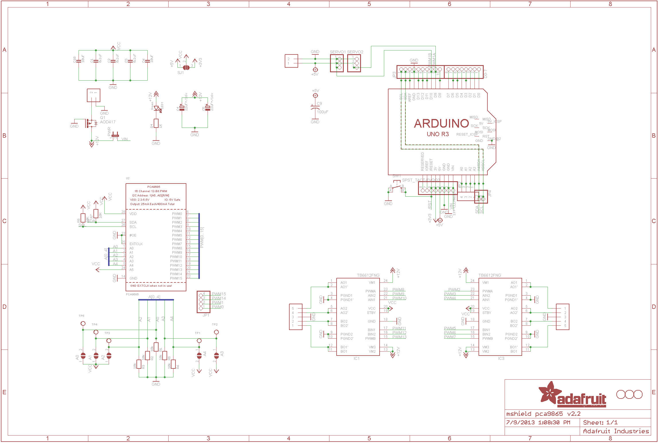
It's just holes. Known as a "matrix prototyping board" for you to solder your own components and things into. Nothing there is connected to anything at all, it's up to you to make the connections with solder and wires.

As you can see from the schematic the only Arduino pins used are SDA/SCL (A4 and A5) and two PWM pins D9 and D10. Everything else comes from the on-board I2C PWM chip.

1
  • Thanks for clearing it up. I found this schematic earlier but it didn't go into detail like you mentioned in your post. Commented Jun 15, 2018 at 10:19

Your Answer

By clicking “Post Your Answer”, you agree to our terms of service and acknowledge you have read our privacy policy.

Not the answer you're looking for? Browse other questions tagged or ask your own question.