1

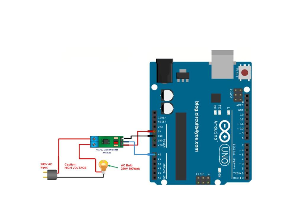
My task is to find the amount of current a light bulb uses, with that motive I used ACS712 current sensor of 30A connected all the connections properly as shown in the circuit diagram below

enter image description here

I tried all different codes available to calculate current...

Arduino Code :

void setup(){
    Serial.begin(9600);
}


void loop(){
  int rVal = 0;
  int sampleDuration = 100;       // 100ms
  int sampleCount = 0;
  unsigned long rSquaredSum = 0;
  int rZero = 511;                // For illustrative purposes only - should be measured to calibrate sensor.

  uint32_t startTime = millis();  // take samples for 100ms
  while((millis()-startTime) < sampleDuration)
  {
    rVal = analogRead(A0) - rZero;
    rSquaredSum += rVal * rVal;
    sampleCount++;
  }

  double voltRMS = 5.0 * sqrt(rSquaredSum / sampleCount) / 1024.0;

  // x 1000 to convert volts to millivolts
  // divide by the number of millivolts per amp to determine amps measured
  // the 20A module 100 mv/A (so in this case ampsRMS = 10 * voltRMS
  double ampsRMS = voltRMS * 10.0;
  Serial.println(ampsRMS);
  Serial.println(analogRead(A0));
}

Output

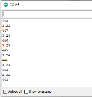
enter image description here

The output remains the same, even when the bulb is still lighting up.

Thank You in advance :)

6
  • print the values of rSquaredSum / sampleCount and voltRMS
    – Juraj
    Commented Nov 26, 2020 at 14:37
  • How much current does your bulb actually use? Or put differently: what percentage of 30A is that?
    – timemage
    Commented Nov 26, 2020 at 14:37
  • @timemage, on the picture it is 230 V / 100 W. it should make a difference in my experience. but it could be lost in calculation
    – Juraj
    Commented Nov 26, 2020 at 14:39
  • That is in part what I'm thinking, but also to make sure his expectations are in line with what the sensor will actually do.
    – timemage
    Commented Nov 26, 2020 at 14:43
  • 1
    Try to tell us the different types of code and the tutorials you followed so we can better narrow down the answer. Commented Nov 26, 2020 at 18:38

1 Answer 1

1

In a comment about rZero = 511;, you wrote:

For illustrative purposes only - should be measured to calibrate sensor.

This may well be the cause of your problem. If, instead of 511, the “zero” of your measurement is around 445, then you end up measuring a non-existing DC current of about 3.23 A. When you turn on the light bulb, you add roughly 435 mA (100 W / 230 V) of AC current. The total RMS current you see is then:

√(3.232 + 0.4352) ≈ 3.26 A

Barely visible at the resolution at which you are printing the result. And this is assuming you are using a 100 W bulb, as shown in the diagram. These bulbs are getting hard to come by. If you are using anything less powerful, you may not see any change in the displayed value.

As a quick and dirty fix, you may replace 511 by 445. A better solution would be to compute the quadratic average of the AC part of the signal alone. In other words, compute:

√(average(current2) − average(current)2)

2
  • how did you conclude that the zero is 445? the time between those measurements is more then 100 milliseconds. it could simply catch the same part of the wave
    – Juraj
    Commented Nov 26, 2020 at 17:14
  • 1
    @Juraj: A constant reading yielding 3.23 A must be 511±66, but the values shown in the serial monitor are only consistent with 511−66. Commented Nov 26, 2020 at 17:16

Your Answer

By clicking “Post Your Answer”, you agree to our terms of service and acknowledge you have read our privacy policy.

Not the answer you're looking for? Browse other questions tagged or ask your own question.