I am trying to design a circuit that wakes my ESP8266 (Wemos D1 Mini) from deep sleep using a shock sensor. I can achieve this using the reset pin but I need it to ignore further requests to reset to give it time to run the code in my sketch. Provided there is still motion it will just continue to reset meaning the code only gets run after the 'shock' stops. I have tried all kinds of things with capacitors and transistors to delay subsequent resets but with very limited success. Can someone please point me in the right direction or suggest an easier way to do this? Many thanks in advance.
-
What kind of "shock" sensor, and what kind of "shocks" are you subjecting it to?– MajenkoCommented Oct 22, 2019 at 23:00
-
I'm using a ky-002 sensor. Shocks will be from slight movement.– TintedCommented Oct 22, 2019 at 23:46
-
Use the fact that GPIO16 is LOW in deepsleep and high otherwise - i.e. if GPIO16 is high, you want to prevent your shocks from effecting the reset pin - a simple OR gate may be all you need– Jaromanda XCommented Oct 23, 2019 at 5:04
-
1@Tinted, why do you commet for JamesB?– Juraj ♦Commented Oct 23, 2019 at 8:25
1 Answer
This is actually somewhat more tricky than you would at first thing.
First off, the "shock sensor" is merely a spring inside a tube. This will create lots of triggers while it's being "shocked", which really is messy.
Secondly, you only want those shocks to make it through to the ESP when you are in deep sleep.
Thirdly, you don't want whatever you connect to adversely affect, or be affected by, other circuitry that is connected to the reset pin.
So you first really need to "condition" the output of your sensor so that it gives a clean pulse that can reset the ESP8266. Then you need to "gate" that signal so it can only get through while the board is asleep.
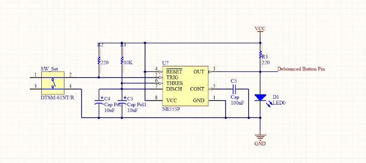
For conditioning the shock sensor signal I would be inclined to use a 55 timer in monostable mode. You can find a good circuit and description here which looks like this:
Now to gate that signal (which is active high) you need a signal to gate it with. Since all the GPIOs of the ESP8266 are "dead" while it's asleep you need it to be in a "default on" state and have the ESP8266 drive an "I am awake" signal to disable the output. So you'd have a pullup resistor on a GPIO to make it default HIGH (to match the trigger pulse for simplicity) and then use pinMode() and digitalWrite() as the first things after waking up (and at the start of setup()) to indicate it's awake by driving it LOW. Then you combine those two signals:
- If the trigger is HIGH and
- If the gate signal is HIGH
- Then pull reset LOW
- Otherwise don't affect reset
So you make a truth table:
Trig | Gate | Res
-----------------
  L  |  L   |  HiZ
  L  |  H   |  HiZ
  H  |  L   |  HiZ
  H  |  H   |  L
The tricky one here is the "HiZ" - This means "High Impedance" - or in effect "Don't affect the reset pin at all".
Apart from that the truth table is that for a NAND gate - if both inputs are HIGH then the output is LOW - otherwise the output is HIGH. Except we want HiZ not HIGH.
To make that HiZ there's two things you can do:
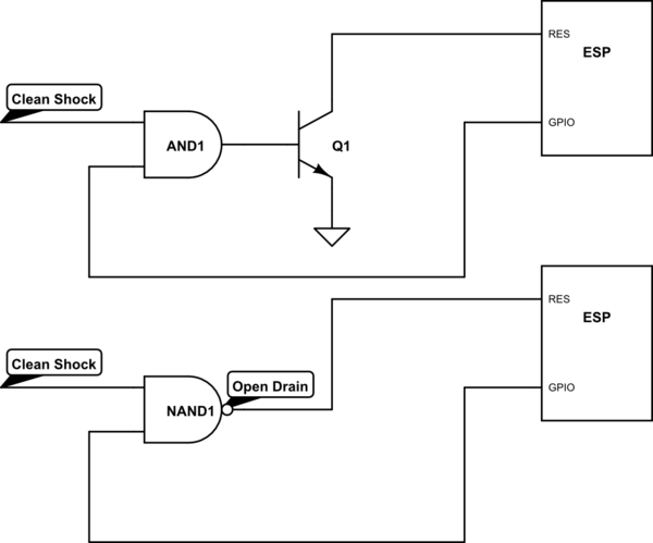
- Use a NAND gate that has an "Open Collector" (or "Open Drain") output, or
- Use an AND gate and create your own "Open Collector" that inverts the output by adding a transistor.
For option 1 you can use the 74AC01 which is a "Quad 2 input NAND gate Open Collector". For option 2 you can use the 74AC08 and any NPN transistor (or N-channel MOSFET with a suitable threshold).

simulate this circuit – Schematic created using CircuitLab

