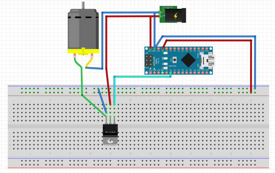
That little blue wire on your breadboard is shorting out the motor.
That is not the problem. That blue wire is actually correct. It connects the source to ground. (-ve)
Your drawing shows the Drain of the Mosfet connected to +12 volts and the Source connected to ground. (the -ve of the supply) If you didn't have the short (blue wire from Source to ground) it still would not have worked.
You can't put an N channel mosfet in the positive side of the supply and control it from a voltage lower than the positive supply. (something the previous answer didn't even mention)
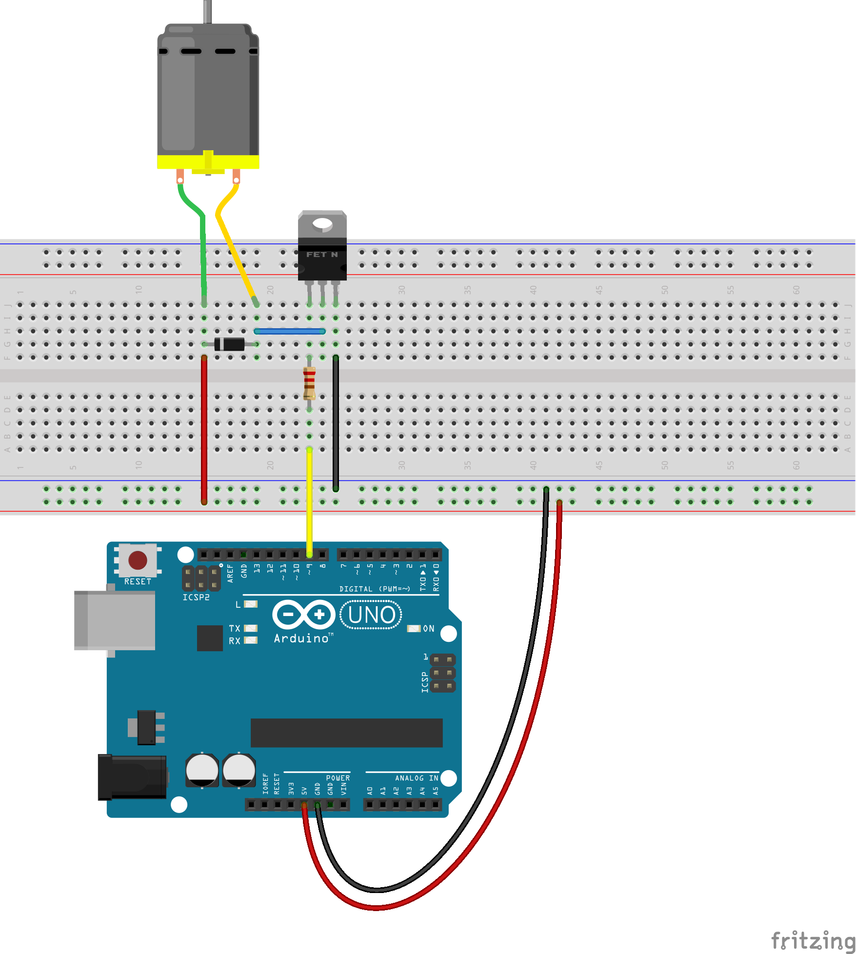
You must have the source connected to ground (as you have) but the drain has to then connect directly to the motor, and the other side of the motor goes to the +12 connection. This would be the correct way, but there still is an important omission. You need to have a diode connected across the motor to control the flyback pulse when the mosfet turns off. Otherwise the voltage spike generated by the motor's inductance will destroy the mosfet switch.
Your blue wire on the breadboard is correct. What is wrong is the red wire to the center terminal of the mosfet. The red wire should be going to the motor. The Blue/yellow connection. The green wire should be going to the mosfet's center pin.And as I said before, there needs to be a diode across the motor, with the cathode (line on the body of the diode) connected to the +ve side of the motor connection.
This is a correct drawing as far as the mosfet and motor connections are concerned. This drawing shows 5 volts being brought to the breadboard to power the motor. In your case this should be the 12 volts from the power supply.

While the beadboard may be adequate for verifying the circuit, it may cause connection problems due to the significant current that the motor will draw. Even if you wired it up properly you may still have issues due to the poor connections.
EDIT:
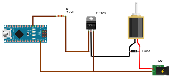
I looked up the specs for the BDX33B and it is a darlington transistor and not a mosfet. But in the end, all that I said also applies whether it was a bipolar transistor or a mosfet. But you need to include a series resistor as shown in the drawing I provided. You can't drive it direct from a port pin as if it were a mosfet.
Another schematic.

This shows a darlington transistor like the one you listed, and a 12 volt power source.


