0

I want to make a small and compact gas sensor using the Arduino Uno and MQ2 sensor. However all sites list a breadboard as a requirement.

Now, the MQ2 has A0, D0, GND, VCC, pins and the Uno also has A0, GND, 3.3V and 5V connectors.

So can I use Male to Female Jumper Wires to directly connect these? I am not using anything else like LEDs or speakers.

My code keeps the inbuilt LED ON when smoke level is LOW and blinks when the Level is HIGH. Also will I need any resistor for it?

5 Answers 5

1

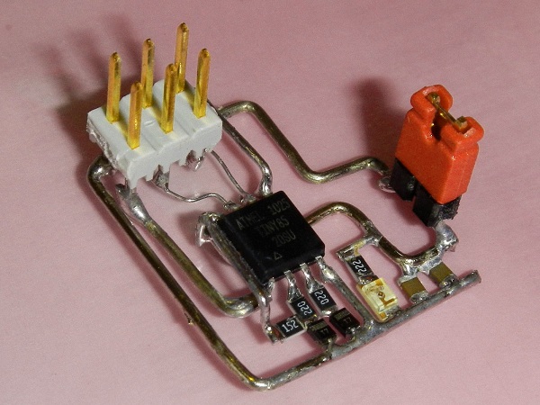
This is point-to-point wiring, a technique loved by high-end audio amplifier fans:

point-to-point

0

Usually I don't think at the UNO as "small and compact"; I usually prefer to use a barebone atmega or an arduino pro mini / nano as alternatives (nano has inbuilt usb, pro mini doesn't). But anyway...

The SeeedStudio MQ2 has four pins, but no D0 pin; it has Vcc, GND and A0 and a NC pin (which means do not connect this pin).

So... Yes, The sensor is 5V powered and has an analog out interface, so you should connect the A0 pin to any analog input on the arduino (A0..A7); you are not forced to use A0.

Be careful that the sensor uses 800mW of power (160mA at 5V) in the pre-heating, so you are not advised to use it form a battery source

0

Yes, you can use male to female jumper wires to directly connect them. Breadboard is not a requirement. Also, you don't need any resistors.

0

MQ2 flammable gas and smoke sensor detects the concentrations of combustible gas in the air and ouputs its reading as an analog voltage. The sensor can measure concentrations of flammable gas of 300 to 10,000 ppm.

The sensor can operate at temperatures from -20 to 50°C and consumes less than 150 mA at 5 V.

Connecting five volts across the heating (H) pins keeps the sensor hot enough to function correctly. Connecting five volts at either the A or B pins causes the sensor to emit an analog voltage on the other pins.

A resistive load between the output pins and ground sets the sensitivity of the detector. Please note that the picture in the datasheet for the top configuration is wrong. Both configurations have the same pinout consistent with the bottom configuration.

The resistive load should be calibrated for your particular application using the equations in the datasheet, but a good starting value for the resistor is 20 kΩ.

DataSheet PDF Here

    * Smoke/Gas Sensor Module project
     * tutorial url: http://osoyoo.com/?p=671
     */
    void setup()
    {
        Serial.begin(9600);
    }

    void loop()
    {
        int val;
        val=analogRead(0);
        Serial.println(val,DEC);
        delay(100);

}
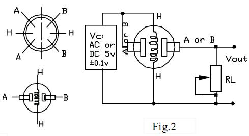
MQ2 - Wiring Diagram

0

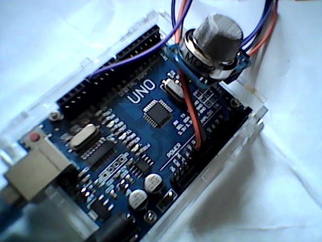
You can connect it exactly like this. I'm using female-female jumper wires and have soldered pins onto the UNO clone to enable me to do this.

MQ2 Connected to Uno R3 Clone close-up showing pins soldered onto board

Pins on sensor from left to right A0 - D0 - GND - VCC

You can also find the wiring diagram on-line for a barebones sensor if you've not got the sensor module.

here MQ2- Sensor Information

You can either use the D0 output pin to turn on an LED in the presence of gas / smoke or you can use the A0 to report a gas / smoke level.

The code in my other reply is for the analogue reporting of the sensor value. The Digital output is either on or off and the potentiometer on the back of the sensor will adjust the point at which the D0 pin report a High output level, if it's not set right then the D0 pin won't actually output a voltage.

Your Answer

By clicking “Post Your Answer”, you agree to our terms of service and acknowledge you have read our privacy policy.

Not the answer you're looking for? Browse other questions tagged or ask your own question.