7

What i saw is that the led use 1.3V on 100mA with a 1:10 Cycle (100ms). Im currently at 30mA using only a 100 resistor, but the range of the led is 20cm at max, i want to get at least 2 meters.

Since i know the max output of the Arduino pin is 40mA i need to use a transistor to get the 100 i want. And that is the problem, i read a lot about how transistors works but i can't yet understand how can i achieve 100mA using a transistor.

I did the math using 5v and got 37R.

Is this correct? So i need to use a 37 ohms resistor to get the 100mA i want?

And this resistor is going between the digital input and the transistor base, correct?

Im using a NPN 2n2222 and reading the datasheet 100mA is easy job for this transistor.

I appreciate any help.

4
  • 2
    you want to saturate the 2222, then pretend avail ma is infinite, resist from there
    – dandavis
    Commented Apr 6, 2017 at 4:02
  • Sorry i forgot to reply, but thanks a lot @dandavis your comment helped me a lot.
    – Luke
    Commented Apr 13, 2017 at 6:22
  • @dandavis what do you mean by "saturate"? what equations should be used?
    – shinzou
    Commented Oct 3, 2017 at 16:49
  • @shinzou: that's now explained in the accepted answer
    – dandavis
    Commented Oct 3, 2017 at 19:08

2 Answers 2

4

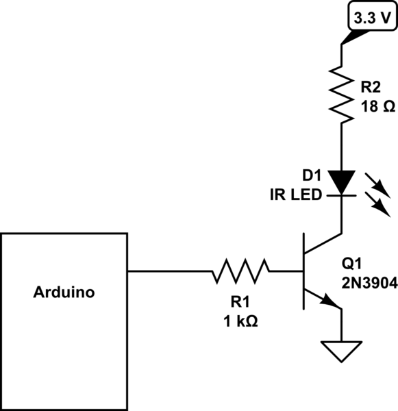
Here is a diagram from Peter Bennett's answer to an Electronics Stackexchange question, How much voltage to give my IR LED?:

transistor driver

As you can see, the current-limiting resistor is in series with the IR LED and the transistor's collector. The base resistor is large relative to the current limiting resistor, because this transistor amplifies base current by a factor like 100.

The 1000 Ω base resistor is ok for loads into the neighborhood of 100 mA; if you plan to drive a larger load, use a smaller base resistor. As noted in the 2N3904 datasheet, hFE may be as small as 30 when IC = 100 mA. To ensure transistor saturation, arrange that hFE*(VCC-VBE)/RB exceeds desired collector current.

2N2222 specifications are similar to those of the 2N3904 mentioned in the question, but hFE drops off more slowly (as IC increases) for the 2N2222.

See the Electronics Stackexchange question linked above for more discussion and further links.

5
  • I have some questions, can i use the 5V arduino output as the source of energy to the led? (in the diagram is the 3.3V input). I did the math here and i got 22.5R for 80mA instead of the 18R he said is nedded to get 80mA, why i got a different number? For the voltage i did 3.3V - 1.5V (the current of the ir led). How can i know the correct number of the base resistor? Could i use lets say a 10kR? Nevermind about the first question, i saw after that the led actually use 1.8V
    – Luke
    Commented Apr 5, 2017 at 21:16
  • I edited a bit about the base resistor, and included an equation about it. With R1 = 10KΩ, Vcc = 5, Vbe = .7, you would get 0.43 mA into the base, and say 43 mA load current (if hFE is 100); so 10KΩ is too much resistance. Re using 5V arduino output for LED current, most Arduinos are ok supplying a few hundred mA to auxiliary circuits like LEDs, if incoming raw voltage is not too high. The descriptions at arduino.cc sometimes say how much current can be drawn through the onboard regulator, but to be certain may require reading the regulator's part number and looking it up on the web. Commented Apr 5, 2017 at 21:49
  • I see, eletricity is hard to gasp but im slowly learning. Thanks for all the help.
    – Luke
    Commented Apr 5, 2017 at 22:01
  • What are the parameters for hFE*(VCC-VBE)/RB in the picture? Also where are they in the transistor's spec?
    – shinzou
    Commented Oct 3, 2017 at 19:32
  • For the 2N3904 shown in the diagram, DC Current Gain hFE and Base-Emitter Saturation Voltage VBE(sat) are shown on page 2 of the spec sheet, in the “ON CHARACTERISTICS” table. Re other parameters used in the hFE*(VCC-VBE)/RB equation: VCC depends on Arduino supply voltage, and RB = R1. Commented Oct 4, 2017 at 3:04
4

Increasing the power to the LED isn't the best way of increasing the distance. In fact it's the worst way.

The 100mA is only for a small duty cycle. You can power it with 100mA but only for a fraction of the time. The overall average light output won't be any more than at 30mA.

The problem you are actually suffering from is the fact that your receiver can't distinguish the LED's light from the background light. That is simple to overcome though. You just need to modulate your LED with a high frequency (typically 30kHz or higher) and perform a high pass filter and amplification on the receiver.

Exactly the same way that remote controls do it.

That way you can distinguish the LED (flashing at a given frequency) from the background light (static brightness or relatively very slowly changing).

1
  • 1
    I know i can only power for a fraction of time. Thats why i said it was a 1:10 cycle (1 cycle on and 10 cycles off with 100ms per cycle). Im already sending the signal with 32kHz and i can't filter the receiver since i didn't make it, im only doing a controller not a receiver. Anyway it worked as far as i know. The led is receiving about 70mA. What was before a 30cm range is now about 7m range. So i guess i did something right sending more amperage. In theory i could go even further and try to reach 80mA but im happy with the final result. Anyway thanks for the tip.
    – Luke
    Commented Apr 7, 2017 at 17:56

Your Answer

By clicking “Post Your Answer”, you agree to our terms of service and acknowledge you have read our privacy policy.

Not the answer you're looking for? Browse other questions tagged or ask your own question.