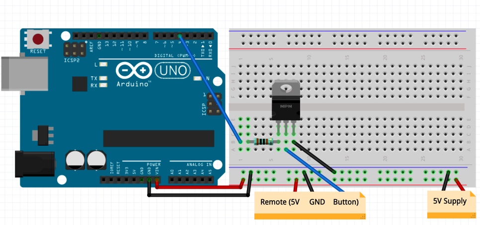
You really only need one wire and no resistors or mosfet.
I see many answers including expensive mosfets and relays to answer this question. There is a much simpler solution requiring no glue logic or interfacing circuitry. I recently had to install an off-the-shelf ultrasonic humidifier in an incubator/brooder. It is the cheap little home-use aromatherapy type diffuser. It had to be controlled by a relay to turn on and off. The catch is that the control circuit and firmware used in nearly all of these is the same, it can be turned on by a relay in the PID incubator controller but requires a single button press once power is supplied to start the ultrasonic humidifier and fan. three button presses turns the humidifier off and returns it to standby and turns off automatically when it runs out of water. using the arduino to control only the button to bring it out of standby would not lead to reliable operation. I searched for an answer but found none that I could make given I had few parts and was working on a remote farm. This is my solution.
The science behind this and how it works is that the microcontroller does not sense the press of a button, it detects a state change. You may familiarize yourself with this in the arduino tutorials for reading a button press.
Tie the arduino ground to ground in the circuit you want to control. find a 5v rail and power the arduino. no extra power required. There is usually a test pad that will be ground and 5v close to the button you want to control. if not, find the regulator for the microcontroller that you are trying to trigger by tracing the circuit and attach the power rails. I used Digital Pin 2 for the trigger signal. connect d2 to a point near the switch. Ensure there is a resistor of about 600-1000ohm in the circuit between the point and the microcontroller. This should be present on the circuit you are triggering already simply because this is how microcontrollers detect state changes without sinking or sourcing infinite current.
This code will trigger once and then go to sleep. The long delays are to allow for expected debounce code in the microcontroller and allow for boot time. put simply, it switches PD2 between high and low states in high impedance and low impedance states and basically all a switch does is switch between high impedance and low impedance states. This code should trigger pretty much any microcontroller regardless of the specific state required once and then go to sleep.
#include <avr/sleep.h>
void setup() {
  pinMode(13, OUTPUT);
}

void loop() {
  pinMode(PD2, INPUT_PULLUP);
  digitalWrite(PD2, HIGH);
  delay(2000);
  pinMode(PD2, OUTPUT);
  digitalWrite(PD2, HIGH);
  digitalWrite(13, HIGH);
  delay(300);
  digitalWrite(13, LOW);
  pinMode(PD2, INPUT_PULLUP);
  digitalWrite(PD2, HIGH);
  delay(300);
  pinMode(PD2, OUTPUT);
  digitalWrite(PD2, LOW);
  digitalWrite(13, HIGH);
  delay(300);
  digitalWrite(13, LOW);
  pinMode(PD2, INPUT_PULLUP);
  digitalWrite(PD2, LOW);
  delay(500);
  sleep_enable();
  set_sleep_mode(SLEEP_MODE_PWR_DOWN);
  sleep_cpu();
}

