1

I have a TIP 120 to 229 NON 60V 5A transistor

I'm trying to use it to switch an electro magnet. Using the blink example to test it out:

// the setup function runs once when you press reset or power the board
void setup() {
  // initialize digital pin 13 as an output.
  pinMode(13, OUTPUT);
}

// the loop function runs over and over again forever
void loop() {
  digitalWrite(13, HIGH);   // turn the LED on (HIGH is the voltage level)
  delay(500);              // wait for a second
  digitalWrite(13, LOW);    // turn the LED off by making the voltage LOW
  delay(500);              // wait for a second
}

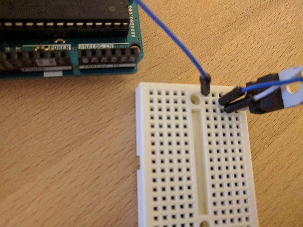
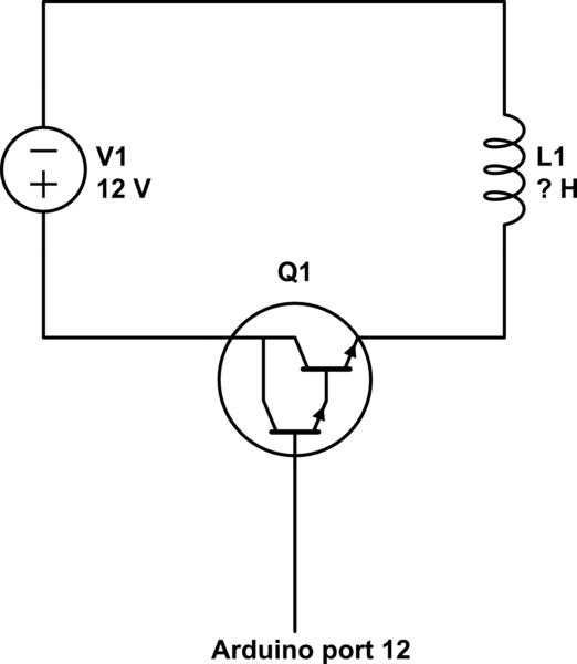
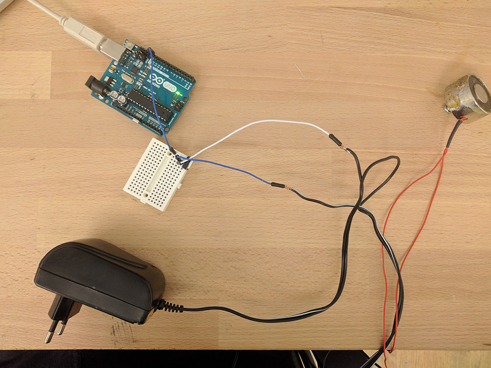
pin 13 is connected to the base and I'm trying to powering the magnet with a 12V DC adapter. I'm not sure if the transistor is before or after the magnet, but I'm not sure how that would make a difference.

I'm not great with diagrams but something like this (the power source might be the other way around:
schematic

simulate this circuit – Schematic created using CircuitLab

I've tried switching between the collector and the emitter. In one instance the magnet is always active and in one instance it's always passive. What could be wrong?

The cords running of the table in the bottom is just a bit of extra wiring. enter image description here enter image description here
11
  • A magnet?!?! Do you mean an Electro-Magnet??
    – Dat Ha
    Commented Oct 26, 2016 at 15:05
  • How about showing a circuit diagram?
    – Majenko
    Commented Oct 26, 2016 at 15:06
  • @canadiancyborg Yes
    – Himmators
    Commented Oct 26, 2016 at 15:09
  • @Majenko sure, gimme a sec!
    – Himmators
    Commented Oct 26, 2016 at 15:09
  • 1
    Uhhh transistor wrong way around in the schematic?
    – Bradman175
    Commented Oct 27, 2016 at 0:35

3 Answers 3

5

Is there the only wire from Arduino to the Base of Transistor?

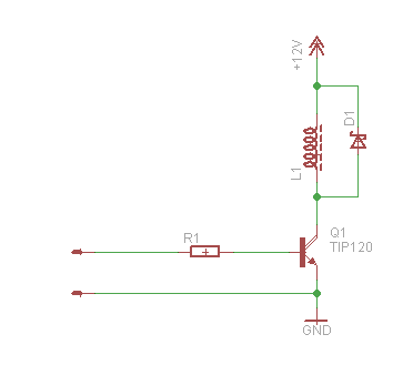
Basically you need something like this:
enter image description here

If you reverse the transistor (E and C), builtin protection diode will be in forward direction, so electro magnet is on.

If you have only one wire to the base, it cannot work as you need current to the base.

If you don't have R1 into the base (about 500R-1K), it'll burn your output eventually. (not if you don't have common ground)

If you have electro magnet between ground and Emitter, you'll have negative current feedback and about 4.2V on L1 tops as there must be some current into the base.

5
  • With reverse transistor do you mean reverse collector and emitter? What is "the base"? I'll put in R1 but would that make this setup not work? I don't have D1 either, what does that do?
    – Himmators
    Commented Oct 26, 2016 at 15:34
  • If the wire marked by white is +12V, it will be the last case, so no. Also you need common ground, but be carefull, I can see the smoke generator more likely...
    – KIIV
    Commented Oct 26, 2016 at 15:40
  • The transistor is connected to on the wire with a white mark, is that the right or wrong wire?
    – Himmators
    Commented Oct 26, 2016 at 15:47
  • White is usually the positive supply. You have to measure it.
    – KIIV
    Commented Oct 26, 2016 at 15:48
  • You need a resistor between the arduino and the base of the darlington transistor.
    – Gerben
    Commented Oct 27, 2016 at 8:35
2

The program is fine.

Looking at the first photograph - The Ground of the Arduino needs to be connected to the ground of your circuit.

I do not understand the two-transistor part of your circuit, so I can't say if this is OK or not. You could also switch the electro-magnet using a relay.

5
  • 2
    I don't understand the two-transistor part of your circuit - It's a Darlington transistor
    – Nick Gammon
    Commented Oct 27, 2016 at 5:34
  • @Kingsley, needs to be connected to the ground ok thanks! Is this likely what's causing my problem or is this for some other reason (trying to learn as much as possible).
    – Himmators
    Commented Oct 27, 2016 at 9:31
  • Can confirm the darlington transistor, concerning the relay, I needed something really fast for my application, so I went with a transistor.
    – Himmators
    Commented Oct 27, 2016 at 9:32
  • Also How would I do ground arduino in practice? Should i run a wire from ground on the Arduino to the negative pole on the 12V DC-converter?
    – Himmators
    Commented Oct 27, 2016 at 15:21
  • @Himmators - Yes, the ground of the arduino should be connected to the power supply ground. Generally all grounds are connected together.
    – Kingsley
    Commented Oct 30, 2016 at 9:08
0

Assuming the - of the power supply is connected to ground your circuit becomes an emitter follower utilizing a Darlington transistor. In that case the emitter will have the same voltage as the base - the VBE which is about 5 Volts. If you reverse it, you will need about 5 volts VBE to turn it on. Note since it is a transistor there is no protection diode. Best suggestion is to use a MOSFET, that will give you a lot more speed then a power transistor. Substitute the MOSFET in the circuit shown above. Source connects to the Emitter point, the Drain connects to the Collector point and the Gate connects to the base. Use something in the 50 Ohm range for the resistor. Your 12V - becomes ground connected to the Arduino ground. Use a logic level avalanche protected MOSFET and the diode is not needed.

2
  • Why don't you add a schematic? Also, I think you overlooked the most important error in the original question, which is that the NPN darlington is used a a high side switch (which is never a good idea for an NPN device). In general, Darlingtons are more robust devices than MOSFETs, especially with inducive loads, so I think it's perfectly acceptable here.
    – StarCat
    Commented Nov 22, 2020 at 9:02
  • A NPN as a high side and a PNP as a low side are emitter follower circuits, not switches as the transistor cannot be saturated. The emitter follower or common collector circuit provides an ideal buffer amplifier and it is easy to design the circuit however a switch it is not. Check this link: electronics-notes.com/articles/analogue_circuits/transistor/…
    – Gil
    Commented Nov 23, 2020 at 21:31

Your Answer

By clicking “Post Your Answer”, you agree to our terms of service and acknowledge you have read our privacy policy.

Not the answer you're looking for? Browse other questions tagged or ask your own question.