0

I'm new to Arduino and haven't done any education in electrical engineering before, so this might be a very dumb question.

I'm busy with a project to control two servo motors with Arduino. Now yesterday I connected the wires incorrectly to the breadboard, so the wires started smoldering. I didn't connect the resistor correctly, so I guess that might have been the problem.

Now I replaced the wiring, but it's not working and I don't know if the software might be the problem or the breadboard need to be replaced as well. I cannot see anything wrong with the breadboard, but it was warm so I don't know if it might be burned from the inside? The wiring of the servomotors seems to be okay, so I guess that I don't need to replace those I hope.

Any tips about how to check everything is still working?

Or might it be a good idea to buy an LED and add it to the breadboard to ensure it's okay?

EDIT: I guess I found some code to check that the servomotors are still okay. Just add them directly to the Arduino and run some code: Sweep

One other question: one of the servomotors doesn't have a black, red and yellow cable but a red, brown and orange. How can I know which ones the same as yellow, red and black?

9
  • I didn't know you could buy just one LED...
    – Majenko
    Commented Apr 18, 2016 at 9:36
  • I didn't connect the resistor right - Resistor? With servos? Can you share your schematic please? It sounds like you are doing something wrong.
    – Majenko
    Commented Apr 18, 2016 at 9:49
  • How did you understand that it was the breadboard? usually a breadboard is a plastic cover and metal contacts; if something is broken, then probably it's the arduino or the servo,..
    – frarugi87
    Commented Apr 18, 2016 at 10:18
  • 1
    @ErikvandeVen usually if you can't understand if it is fried then it is not fried. When a breadboard "blows" the white plastic becomes black (and even then most of times it still works). To be sure, assemble your circuit, then check with a multimeter the resistance between each pin and the servo. I mean, touch the GND pin on the arduino and the GND pin on the servo and check that the resistance is low. Then do the same for the +5V and the signal..
    – frarugi87
    Commented Apr 18, 2016 at 10:35
  • 1
    haha I'm sorry. yes I meant if, my bad. Commented Apr 18, 2016 at 12:39

3 Answers 3

1

To answer your last question (for 99%):

red = +
brown = gnd
orange = pwm (speed)

To test: try measure resistance with multimeter, gnd and + should have the lowest resistance.

And to be save: buy a new breadboard, a bad partly melted breadboard, or pieces of solder spoiled, is a nightmare.

Otherwise you can test with a multimeter the resistance of your breadboard for columns (close to 0) and rows 1.

1
  • And if you want to be more sure, 99.99% of times the pinout is always the same, so if your cables are black-red-yellow and the other is brown-red-orange, then brown GND, red + and yellow PWM
    – frarugi87
    Commented Apr 18, 2016 at 10:17
2

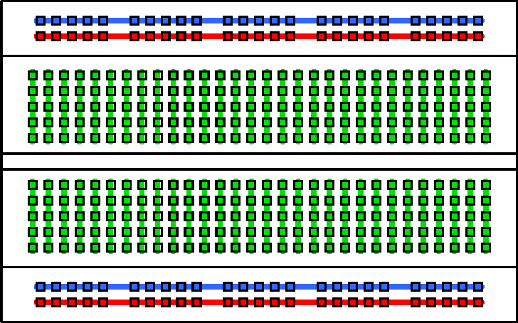
You could check the connections of the breadboard, using a multimeter (set to continuity check) and wires in the breadboard holes, with the + and - leads, from the meter, at either end of each row/column of connections, following the diagram below:

Breadboard connections

It might be a bit tedious, but it should only take thirty minutes maximum, and would give you peace of mind as well as saving you four Euros...

If you say that it was working before and now is not, then maybe the breadboard is damaged. However, it is unlikely that the whole breadboard is... try moving your components to a different part of the breadboard.

The breadboard could possibly get warm, as servos can use a fair bit of current, and breadboards aren't really designed for power circuitry. You may be better off using an Arduino Servo shield and connecting the servos directly to that, rather than using the breadboard. Why are you using a breadboard - can you, as Majenko states, provide a schematic diagram?

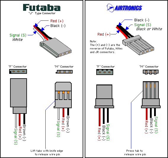
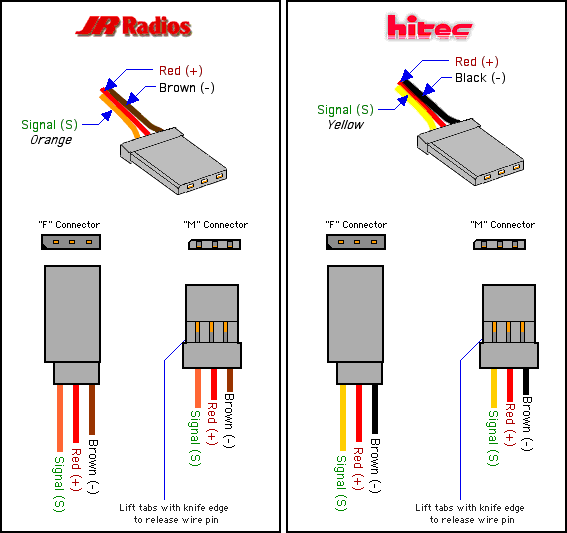
Answering the last part of your question - Taking the graphics from my answer to Code to control servo with shield, to show the different colours for the four different connector types:

Futaba and Airtronics connectors

Futaba and Airtronics connectors

Hitec and JR Radio connectors have the same pin out:

JR Radio and HiTec connectors.

This means that the red, brown and orange leads go to a JR Radios connector.

1
  • @ErikvandeVen - I have updated my answer a little, w.r.t. using the breadboard (component placement and heating) Commented Apr 18, 2016 at 15:55
0

Not all servo motors have the same color cables, that's the manufacturers choice, although they should be standardized. You can test them with a multi-meter, low resistance is usually ground, slightly higher one is usually is usually the power, the other will be the signal. Breadboards are generally cheap and if you suspect yours is not functioning properly, buy a new one. I have two of these and they work very well for $10. MPJA powered breadboard

Additionally, if you have a motor driver shield, they usually have a three pronged port for your servo cable to connect to. Try that as well.

Your Answer

By clicking “Post Your Answer”, you agree to our terms of service and acknowledge you have read our privacy policy.

Not the answer you're looking for? Browse other questions tagged or ask your own question.