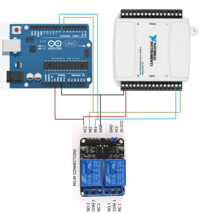
I guess, that you drive the digital pin of the Arduino directly with digitalWrite() for HIGH and LOW and that the DAQ does the same (I didn't researched this).
In that case your circuit is dangerous for the devices. As long, as they both output the same, everything is ok. But take the case, that the Arduino is driving it's pin HIGH, while the DAQ driving it LOW. That would be a short through the pin driving circuit's of both devices and most likely the flowing current will exceed the maximum current rating of the pin. This can fry the involved pins hardware or even the complete devices. You get some kind of race condition here: The device, that can handle drain/source more current will be the winner.
In general you have to implement rules, how the devices should work together. Do you need the actions from the DAQ to be executed no matter what the Arduino does? Or should the Arduino be the master here? Or something inbetween? It is not clear, what do you need here.
I will give you 2 suggestions about possible ways:
You could control the relay only with the Arduino. The DAQ can be connected to a digital input of the Arduino (so that it can sense the DAQ's output state) and in the Arduino code you can implement all the logic you need to drive the relay to your liking.
You could define an idle state of your relay input and set it with a pullup or pulldown resistor. It will ensure, that the relay input is at the defined idle state, as long as no device is driving the line to the opposite state. For this you need the devices outputs to be high impedance (on the Arduino this means the pin is configured as input; for the DAQ you need to know yourself or research it).
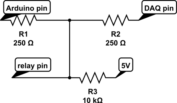
Let's say the idle state would be HIGH. We would connect the relay pin with 5V through a high resistor (this is the pullup resistor) (maybe 10k, the value is not critical). Both devices can be connected directly. If one device needs to change the state to LOW, it can drive it's output pin actively low, forcing the relay pin to also go to LOW. If it doesn't need the state to be LOW anymore, it should put it's pin into high impedance mode. The pullup resistor will pull the state to HIGH again. You can also add relatively low resistors between the devices to protect against damages from accidentally driving active HIGH while the other is LOW (These can be calculated from the maximum current rating for the pins; 20mA for the Arduino). This kind of logic is often called open drain logic.

simulate this circuit – Schematic created using CircuitLab
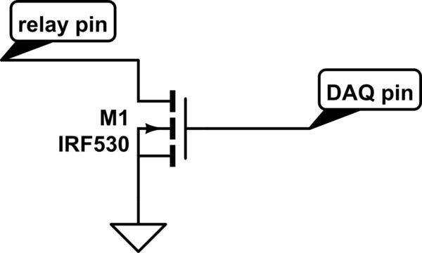
If the DAQ cannot put it's pins to high impedance, you can setup that circuit yourself with a single MOSFET:

simulate this circuit
If you use this circuit on both devices, you don't need the small resistors anymore.
The second possibility already implements a specific logic. You need to decide if this logic is good for you. You can invert it's logic (idle state LOW). Personally I would go with the first option, because it is easier and more flexible.


digitalWrite(portnum, HIGH)orLOW? You might be able to solve this with a pair of diodes.