1

I was wondering if it is possible to create diffrent voltages by just pulsing power into a capacitor,

Im using an esp32 which can only output 3v or nothing on its GPIO pins, and i need to make it possible for it to adjust the amount of voltage without anyone touching the device, so i thought maybe you could pulse 3v into a capacitor and the capacitor would only unload what ever the pulses would give in voltages combined, so e.g. 50% 3v 50% 0v, then it gives 1.5v, i have no idea how this would work or the physics behind it

all help would be appreciated

1 Answer 1

2

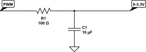
Yes. That's basically PWM through a Low Pass Filter.

Use PWM to set the "duty cycle", which is the percentage of voltage. Then ise a low-pass filter (an inductor + capacitor, or resistor + capacitor) tuned to filter out the carrier frequency (should be around 500Hz if it's the same as an Arduino) to give you a voltage that is proportional to the duty cycle.

schematic

simulate this circuit – Schematic created using CircuitLab

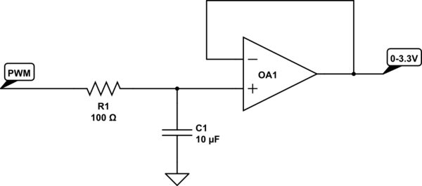
That should filter at about 150Hz. The bigger the capacitor the smoother your output will be, but the slower it will be to respond to changes in the specified voltage. Note that this is not going to give you large currents, but is fine for using as a reference voltage. To boost the current you can feed it into a voltage follower:

schematic

simulate this circuit

4
  • Just a question: why the resistor is just 100 Ohm? I think having it around 10k is better; this way you can have a smaller capacitor and lower currents. According to your experience is having <1k resistor an advantage?
    – frarugi87
    Commented Jun 11, 2021 at 14:41
  • The smaller the resistor the lower the impedance and the higher the current it can supply. If you x10 the resistor you can /10 the capacitor and the frequency response will be the same, but current in and available current out is reduced. 100r is just the default value in the schematic editor and I sized the capacitor accordingly. The choice is entirely yours what values you use.
    – Majenko
    Commented Jun 11, 2021 at 15:00
  • BTW, this is a very handy low-pass filter calculator.
    – Majenko
    Commented Jun 11, 2021 at 15:01
  • ok thanks ;) yes, the output current is directly related to the resistor, but since you put an op-amp just after (so current is virtually 0) I did not understand it. Honestly I did not consider the first schematic, where the lower resistor makes more sense ;) Thank you
    – frarugi87
    Commented Jun 11, 2021 at 15:26

Your Answer

By clicking “Post Your Answer”, you agree to our terms of service and acknowledge you have read our privacy policy.

Not the answer you're looking for? Browse other questions tagged or ask your own question.