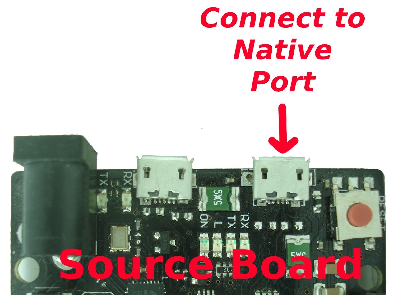
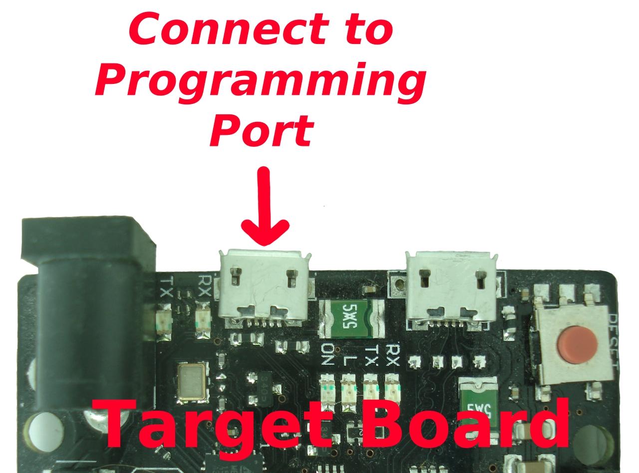
You can use JTAG and probably should. But, it can also be done with bossac if you are very careful. If you're not, you'll end up erasing your flash on your source board.
Using bossac
This would maybe not be preferred over JTAG because it is probably easier to screw up (see warnings below), but it can be done. I may add some on JTAG programming later, and if I do it may be above this section for that reason. The main advantage here is just that you don't need a JTAG programmer. The one caveat is that your existing sketch, or rather the image of the sketch that has been burned onto what I'm calling the "source board" has to be functioning well enough that it can cooperate in being placed back into the ROM bootloader. I fully expect this is not a problem for you, or for pretty much any normal Arduino sketch that has been burned to a board.
WARNINGS
Under NO circumstances do you want to connect to the PROGRAMMING port of your source board at 1200 baud.
Doing so will erase your board, and then that's the end of it.
In the below you will be connecting to the Native USB port at 1200, NOT the programming port.
Connect only one port at a time to your computer so there is no possibility of selecting the wrong one.
Practice this whole procedure with a board you don't care about first.
Locate your BOSSAC command.
On my Windows machine, it was in:
C:\Users\username\AppData\Local\Arduino15\packages\arduino\tools\bossac\1.6.1-ardunio\bossac.exe
It may be under a different version number. It's possible that it will be in a completely different location.
cd %USERPROFILE%
dir bossac.exe /s/b/p/a
Should locate it it, eventually, in any case.
On Linux it will be under ~/.arduino15 somewhere:
find ~/.arduino15 -name bossac
On a Mac it will probably be under a /Library/ directory under the user account somewhere. You get the idea, locate it, make sure you can run it.
NOTE: There's a bossa program that is the GUI version where bossac is a command-line program. Unfortunately the IDE board support files don't ship the GUI program. If you're having trouble with the command-line and want to try that instead, go for it. But test it on a board you don't care about beforehand. I have not tried it.
Connect to the Native Header
Connect your native USB port on the source board and only to that port.

Enable boot to ROM
Open a terminal emulator of your choice at a rate of 1200 baud to the native USB port, wait a couple seconds and then close the port. You can use the Serial Monitor from the IDE to do this if you want:
Select the correct port from Tools/Port.
Open the Serial Monitor
Switch the baud rate to 1200 baud.
You're not going to type anything and you're not going to see anything once you're connected at 1200 baud.
Close the Serial Monitor
You probably should:
See if the port has changed COM#, if so select the new one.
Re-open the serial monitor
Change the baud rate again to anything-but-1200-baud
Close the serial monitor again.
This is not strictly necessary but the IDE remember the last chosen baud rate, and for what we're doing this is a slightly dangerous thing.
Close the IDE as well.
What connecting at 1200 baud does is activate the code inside the core part of the programmed sketch that changes the board to boot from the internal ROM bootloader. It doesn't need traffic. It just needs to see a request for 1200 baud. More specifically, it needs to see the DTR "signal" go inactive, which happens when the port is closed, when the effective rate was 1200 baud.
NOTE: if you screw up here and connect to the programming port at 1200 baud instead, you'll wind up causing the ATMega16U2 to erase your source board. The IDE remembers your last chosen baud rate, which makes this easy to screw up as well. Hence the weird little dance in the above instructions regarding reopening the serial monitor and changing to something other than 1200 baud. It's just putting an extra barrier up to accidentally doing this.
Once you've connected to the native USB port at 1200 baud and closed the port, your board will not run your sketch any more. It's still there, it's just not running it. The board has been told to sit in the ROM based bootloader, waiting for bootloader commands.
Saving your existing sketch's image
What we're going to do is run the bossac command you found earlier like so:
bossac --read saved-sketch-image.bin --boot --reset
I'm assuming you either changed directory to where bossac.exe is, or alternately you're going to specify the necessary path to it found earlier. I've found this command locates the correct COM port automatically.
This command:
Downloads all of flash, 512 kbyte, and takes while, 128 seconds in one test. Weirdly the same version under Linux takes closer to 10 seconds; I haven't looked into why the difference, but I'm also unconcerned.
So you now should have a 512 kbyte raw binary file containing your sketch image.
It re-enables the boot-from-FLASH so that on the next reset it will go back to running your sketch
It resets your board, so it will begin running your old sketch. If you don't want it to do that until you power cycle it, you could just as easily leave off the --reset part.
As said, this is a raw binary file. But you mentioned a HEX. I'm assuming you didn't mean that literally, so I'm not going to detail how to convert the .bin file to a HEX format. Though, if you want to do that, you should know that it needs to be offset to 0x80000, because that's where flash starts on the Due.
Disconnect your source board from USB.
Making your clone (target) board
Connect to your target board via the programming port.

Hold the erase button for a few seconds to make sure the target board is erased. Usually this would be done by the IDE connecting to the port for a while at 1200 baud. But since we're using bossac at the command line, we need to do that step manually; it's just easier to use the button this time.
Reset the board with the reset button. Your target board is now sitting in its ROM bootloader awaiting commands.
Put your image on the new board with:
bossac --write saved-sketch-image.bin --boot --reset
Again, it's programming the whole 512 kbytes. In one test on Windows it took about 100 seconds; no difference between Windows and Linux. We're using the USART (programming port) which is slower than USB and we're flashing rather than reading which is slower; I haven't bothered to figure out which thing is the bottleneck.
Like before --boot sets the board to boot from flash (your sketch) on next reset.
And again --reset just resets the board.
Your target board should now be be behaving identically to the original source board.


-U flash:r:filenameoption