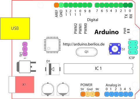
The link you provide looks rather old and I don't think it applies to UNO Revision 3 as it has more pins than on the diagram you show.
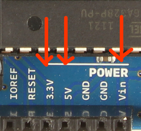
I suggest you rather take a look at this Arduino UNO link which contains uptodate information about the UNO; in there you will see that for R3, the "power rail" has been extended and has the following pins, left to right:
- 1 unlabeled pin (can't remember what it is)
- 1 IOREF pin (used by shields to know if they should operate as 3.3V or 5V devices)
- 3.3V regulated output
- 5V regulated output
- 2 GND pins
- Vin pin: this pin can be used in 2 different ways:
- either as a voltage supply input (instead of using the power plug or the USB); the input voltage should be in 7-12V range and will be regulated internally (by the board circuits) to 5V
- or an output supply voltage (if you plugged voltage supply through the power plug or the USB plug) that is a "copy" of the voltage input through the power plug or USB plug (not regulated yet)


