-3

The problem here is that I want to connect 5 input buttons to an Arduino but I do not want to utilize 5 input pins of Arduino, is there any matrix like connection using which I can reduce the number of inputs used. The conditions here are:

  • All the buttons will be connected to ground and initialized using:

    pinMode(PIN_NUMBER, INPUT_PULLUP)

  • Only digital input is required and not analogue

17
  • 2
    @ShaktiPhartiyal is that "one terminal always connected to ground" an actual restriction or did you add that restriction hoping to make the solution easier? Because without that restriction (and a few diodes), two digital IO pins are totally sufficient, with that restriction, you need an analog input pin, or extensive external logic circuitry, or one pin for every button. Commented Jan 9, 2020 at 14:58
  • 3
    @MarcusMüller I sense XY problem.
    – winny
    Commented Jan 9, 2020 at 15:03
  • 5
    @ShaktiPhartiyal you make our and your own life difficult by adding restrictions like the ground connections and no analog input. You will get more suggestions if you leave things as open as you can, so ask: "How to detect which (of 5) button is pressed while using as few pins as possible on my microcontroller." Then you might get some suggestions. Look at the suggestions and see if that suits your needs. If you have restrictions then make clear why they are there, you will need to have a good reason. An "I don't like analog inputs" for example isn't a good reason. Commented Jan 9, 2020 at 15:12
  • 1
    @Nick How is this Arduino question more then EE? It is pretty valid for any MCU with limited pins available.
    – Maple
    Commented Jan 9, 2020 at 19:47
  • 1
    And yet you accepted Andyaka's answer, which requires you to generate an analog voltage to control the PWM chip. Do you have a real concern about noise, or are you just being superstitious? Anything involving switches is going to have to deal with debouncing (a form of noise) anyway.
    – Dave Tweed
    Commented Jan 10, 2020 at 18:26

4 Answers 4

2

Only digital input is required and not analogue

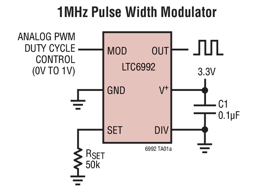
I'd consider arranging the switches to produce different voltages depending on which button was pressed and feed the resulting analogue signal level into one of these (the MOD input): -

enter image description here

It doesn't need to run at 1 MHz of course; RSET can be chosen to make it free run at (say) 1 kHz. The resulting duty cycle (set by the switches) can be read under software control via a digital input line.

1
  • 1
    so this shows how to read analog level with a digital pin and this is the accepted answer. then something is missing in the question. it is a X->Y question and we don't know the X problem and why analog pin can't be used
    – Juraj
    Commented Jan 10, 2020 at 10:07
5

If all switches have one input grounded, you cannot use matrixing.

In any case, the best you could do would be a 2 * 3 matrix, which uses 5 signals, the same as individual switching (though you may be able to share the strobes with other signals e.g. display strobes)

If you are allowed to use an analog input you can pull the input high with one resistor, and allow each switch to pull it low with a different resistance. Then each switch results in a different analog voltage and you can decipher an ADC reading into a switch input. That way, only one input is required.

1
  • Assuming no ground connection: You could totally do this with only 2 GPIO pins (with internal weak pullups), 5 switches, 2 diodes, 2 resistors: One switch to from one each of pins to a resistor to ground (check by checking input voltage) 2 switches between the GPIOs, differentiated only by the direction of their series diodes and one without a diode (check by putting the other pin to output mode, low output voltage, and see whether that changes the "high" state"). Commented Jan 9, 2020 at 18:13
2

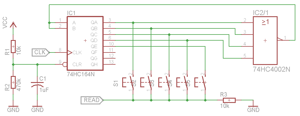
If you do not want to use analog input but not opposed to adding one more component then you can get by with 3 digital pins, two connected to shift register (e.g. SN74HC164) and one reading common return from all buttons. Binary counter can also be used, but with rather high latency.

If you are OK with complicating things even more, you can use external logic for initializing the register, in which case two pins would be sufficient - one for clock output and another for feedback input.

Here is a simple circuit that can be extended to scan any number of buttons by chaining registers or choosing chips with more bits.

enter image description here

Unlike the answers stretching "digital input" function (as implied by OP) to include PWM and Serial communication, this method uses simplest digital I/O: one pin cyclically selects the button, another reads whether it is pressed or not.

The same 2-pin principle (selector output + feedback input) can be used in many different combinations. For example, you can have one side of each switch connected to the ground, as you mentioned in your question. The other sides are fed back to Arduino via analog MUX (e.g. 74HC4051). The MUX address is selected by binary counter (e.g. 74HC193) and the counter is reset by its own QD pin when it reaches 0x08.

2

If you have only one digital pin available, you might consider the 1-wire bus. For example, the DS2408 provides 8 open-drain GPIO pins.


If you can use an analog input pin, then Brian's answer is correct.

Some simple adjustments of the resistor values create equal-size voltage steps for the A/D converter as shown below.
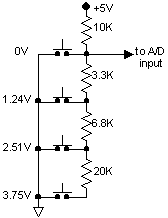
schematic

For the 4-switch case, this gives 5V for no switch pressed, and 0-3.75V in approximately equal steps for a switch press. This approach works well up to 16 switches and beyond.

The general approach for calculating the resistor values is as follows:

  1. Select the pullup resistor value; say, 10K ohms.
  2. Decide how many switches are required: N = 16.
  3. The top switch generates 0 volts by shorting the A/D input to ground.
  4. The next switch down will generate Vcc / N volts:

    R = 10k × 1/(N-1) = 666.7 Ω

  5. Select the nearest standard 5% value: 680 ohms

  6. Repeat for switches i = 2 through N - 1:

    • The next switch down will generate Vcc × i / N volts, but you must subtract out the values of the resistors above it. This helps avoid cumulative errors.

      R = 10K × i/(N - i) - 680 Ω - ...

    • Select the nearest standard 5% value.

For the specific example of 16 switches, you should end up with the following resistor values: 680, 750, 910, 1000, 1200, 1500, 1800, 2200, 2700, 3900, 5600, 7500, 13K, 27K and 82K. Even with 5% resistors, all of the resulting voltages are within 0.25% of full scale of their nominal values.

Your Answer

By clicking “Post Your Answer”, you agree to our terms of service and acknowledge you have read our privacy policy.

Not the answer you're looking for? Browse other questions tagged or ask your own question.