If you have only one digital pin available, you might consider the 1-wire bus. For example, the DS2408 provides 8 open-drain GPIO pins.
If you can use an analog input pin, then Brian's answer is correct.
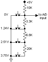
Some simple adjustments of the resistor values create equal-size voltage steps for the A/D converter as shown below.
For the 4-switch case, this gives 5V for no switch pressed, and 0-3.75V in approximately equal steps for a switch press. This approach works well up to 16 switches and beyond.
The general approach for calculating the resistor values is as follows:
- Select the pullup resistor value; say, 10K ohms.
- Decide how many switches are required: N = 16.
- The top switch generates 0 volts by shorting the A/D input to ground.
- The next switch down will generate Vcc / N volts:
R = 10k × 1/(N-1) = 666.7 Ω
- Select the nearest standard 5% value: 680 ohms
- Repeat for switches i = 2 through N - 1:
The next switch down will generate Vcc × i / N volts, but you must subtract out the values of the resistors above it. This helps avoid cumulative errors.
R = 10K × i/(N - i) - 680 Ω - ...
Select the nearest standard 5% value.
For the specific example of 16 switches, you should end up with the following resistor values: 680, 750, 910, 1000, 1200, 1500, 1800, 2200, 2700, 3900, 5600, 7500, 13K, 27K and 82K. Even with 5% resistors, all of the resulting voltages are within 0.25% of full scale of their nominal values.

