0

I want to control about 20 leds with an arduino mega. This leds works with 12v voltage.

I tried to put 20 relays but this solution is not good for me because leds will often blink

I have also tried transistors but it needs to make a pcb.

I am looking for a solution without having to create a pcb

Any idea ?

Thanks

3
  • something like this perhaps? i1.wp.com/media.boingboing.net/wp-content/uploads/2017/07/…
    – jsotola
    Commented Jul 10, 2019 at 9:51
  • You need to be able to turn these LEDs on and off individually? If you only need to turn them all on or off as a group you could use a single transistor.
    – Duncan C
    Commented Jul 10, 2019 at 12:55
  • If you're using relays correctly then your LEDs should not blink. There are "digital" relay modules that are made to be driven from 5V CMOS logic, but 20 relays will take a lot of power. Transistors are a much better bet.
    – Duncan C
    Commented Jul 10, 2019 at 12:55

4 Answers 4

2

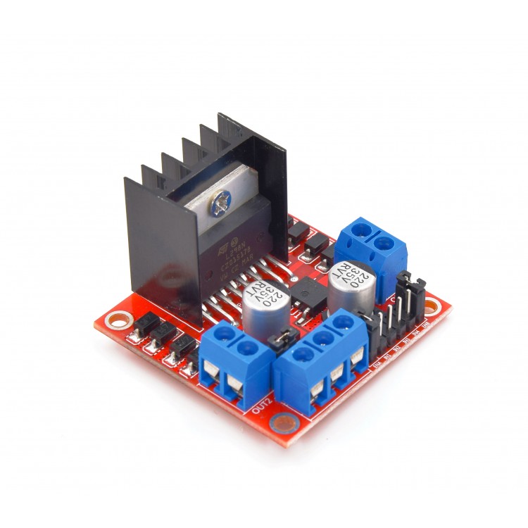
You can use the commonly available L298N module to drive four of your LEDs with each module. That means you would need five of them. L298N module Those modules are suitable for driving either one stepper motor, two DC motors (in both directions), or four "unidirectional" loads such as your LEDs.

The input can be connected directly to your MEGA, but you may need additional series resistors depending on the LED you use (though this likely does not apply for LEDs specified as "12V").

There are also LED driver eval boards available which may suit your needs: https://www.digikey.de/product-detail/de/adafruit-industries-llc/1455/1528-1019-ND/4990768

2

The ULN2803 is a chip with 8 darlington transistors in it designed for driving higher voltage, low-ish current, loads like this. With 3 of them you have 24 channels to drive your LEDs.

You can get them on a breakout board quite easily, or as a DIP chip for working with breadboards.

1
  • This sounds like a good solution. A DIP package with 8 darlingtons on it should be able to handle 8 LEDs, and 3 DIP chips would fit on a pretty small breadboard or PCB. Transistors are better/easier to deal with than relays for modest current DC loads like this anyway.
    – Duncan C
    Commented Jul 10, 2019 at 13:09
1

Three TPIC6B595 shift registers, controlled by 3 pins from the Mega, can do this easily. Shift in 3 bytes with on/off state of the LEDs. Can sink 150mA per output from 12V source. The LEDs need current control, from simple resistor for 20mA loads, to a constant current driver per LED for higher current LEDs.

I used them to sink current from 12V for the LED strings in this display. The small digits needed ~ 20mA per segment, the larger digit is really 2 groups of 3 LEDs, drawing about 40mA per segment. One shift register per digit.

https://www.youtube.com/watch?v=6HZ0Mr51jUY

0

Try s MOS- FET transistor. Its not expensive and easy to drive. Can be directly connected to the Arduino. Look for standard circuit diagrams. 1 P- Mos Fet and 1 Resistor per channel, esch can drive several Amperes st 12V...

2
  • You don't need gate resistors for logic-level MOSFETs. They have capacitive inputs just like CMOS logic chips, and draw almost no input current.
    – Duncan C
    Commented Jul 11, 2019 at 1:39
  • Connecting up 20 single transistors would be really tedious, vs 3 chips. I even made a board with a 328P, FTDI module, and 3 shift registers to drive 24 LEDs for an hours/5 minute intervals clock display. Very compact, about <25x50mm if I recall. Board with 4 shift registers to coontrol gates of 32 MOSFETs to drive larger loads with screw terminal connectors was much bigger, 100mm x100mm. And no microcontroller.
    – CrossRoads
    Commented Jul 16, 2019 at 19:32

Your Answer

By clicking “Post Your Answer”, you agree to our terms of service and acknowledge you have read our privacy policy.

Not the answer you're looking for? Browse other questions tagged or ask your own question.