1

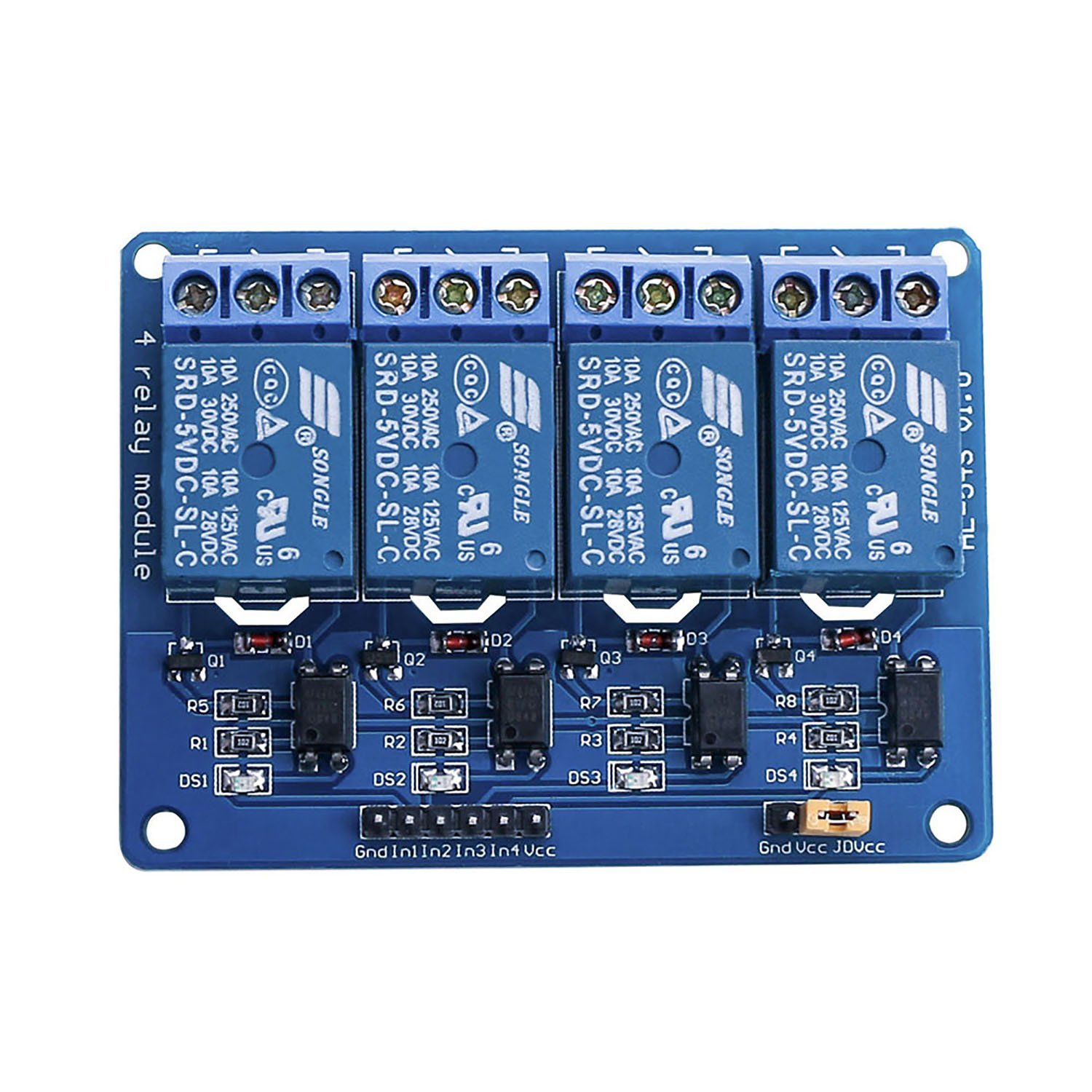
I am trying to setup my first relay module with live environment. I have attached the relay module image below.

enter image description here

Which I am using to control 4 devices in my switch board as follows:

  1. Fan (working fine),
  2. 6w celling LED panel (2 connected in series) (Working fine)
  3. 15w celling LED panel (2 connected in series) (Sometimes work sometimes don't)
  4. Spotlights 3 lights in series and some LED strips connected to it (Sometimes works sometimes don't.).

I have cut one wire which is connected to main normal mechanical switch WHICH IS NOT A HOT WIRE its just the another wire connected to the button.

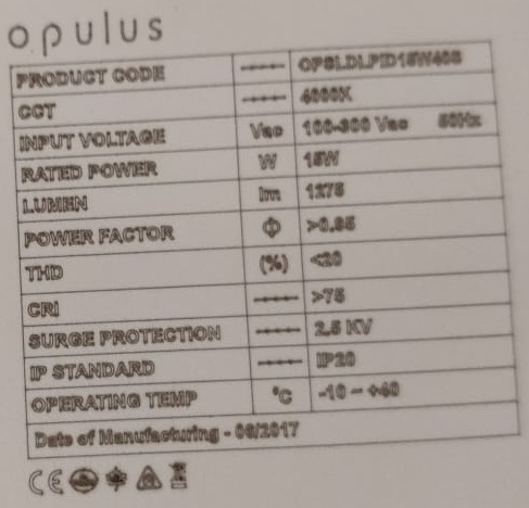
But I am not sure why its not working? Do I need to connect neutral to the another end of the relay. As I have only 2 wires connected to the relay for each of the switches. Here is a screenshot of specifications 15watt LED panel which is connected to my house, if this can help to understand better.

enter image description here

If I connect Neutral on the first pin of relay and when I close the relay switch, do the current will go into the neutral wire as well?

If I keep my 3w spotlights ON or more then 3-4 hours and try to close the relay on connected to it. The relay LED light for that connected relay goes OFF but the light don't. Seems like the mechanical relay is not getting enough power to move the mechanical relay off.

I want to know why this is happening? And how can I solve this issue? Attaching a neutral (earth) wire will help to reduce this? But if connect neutral to first (off side of relay) pin, then will get the current?

Any suggestions will be helpful. Also I added 3.3v from NodeMCU to VCC (instead of jumper) pin. But that is also not helpful.

13
  • NodeMCU don't have 5V pin. I have only 3.3v pins. do I have to connect to any buck converter? @Juraj Commented Jan 9, 2019 at 7:09
  • How are you powering the nodemcu? The relay needs 5V minimum (72mA current per relay, by the way, so that's 288mA you'll need just for the relays) I mean, the clue is in the name ... they are 5V relays Commented Jan 9, 2019 at 7:36
  • @JaromandaX I am powering it with mobile charge which is 5v Commented Jan 9, 2019 at 8:10
  • 3
    the Vin pin will be 5V Commented Jan 9, 2019 at 9:10
  • 1
    This "question" is vague and confused - I would STRONGLY ADVISE that you you do not attempt to connect to mains power - there is a danger of electrocution. No electrician would even consider connecting neutral to a relay (or any kind of switch).
    – Milliways
    Commented Jan 9, 2019 at 10:52

1 Answer 1

0

You need to connect Vin from NodeMCU (Raw 5V from USB) to Vcc on the relay board.

And as stated in the comments, the relay need 5V for operating reliable.

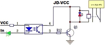
In has the same problem, two LEDs and a resistor. To enhance it would be to replace the indicator LED (DS1-4) with a wire.

2 x LEDS á ~1.8V and a resistor á ~1.4V = 5 Volt.

1 x LED á ~1.8V and a resistor á ~1.4V = 3.2 Volt.

enter image description here

11
  • but if the JD-VCC is not connected with VCC and JD-VCC is 5 V and VCC is 3.3 V then it will work wit 3.3 V io pin without modification? I am a programmer and not good in electronics, but it is how I read this circuit.
    – Juraj
    Commented Jan 9, 2019 at 17:53
  • One of the purpose with JD-VCC is to be able to have a optical isolation between "In" and the relay circuit and another is that you can have one PSU that feed the relays.
    – MatsK
    Commented Jan 9, 2019 at 18:27
  • So do you think any step up (3.3v to 5v) buck converter can solve the problem? Commented Jan 9, 2019 at 18:33
  • 1
    If you remove or shorten the LED then you can drive the in with a 1.8 volt lower voltage, 5V - 1.8 volt = 3.2 volt.
    – MatsK
    Commented Jan 9, 2019 at 19:00
  • 1
    Please read the answer.
    – MatsK
    Commented Jan 12, 2019 at 12:29

Your Answer

By clicking “Post Your Answer”, you agree to our terms of service and acknowledge you have read our privacy policy.

Not the answer you're looking for? Browse other questions tagged or ask your own question.