1

I spent on this question more than 2 weeks of googling with no success. I do not get a response from ESP8266 version 01 on AT commands. I need to access Wi-Fi from Arduino via ESP8266-01. I know that ESP8266 can be programmed to work without Arduino and so on, but I need it to be a Wi-Fi module for Arduino. On most of the websites Arduino is used as UART for direct programming of ESP8266-01, but I am making this setup to make it work as a Wi-Fi support for Arduino:

  esp       Arduino
  ---       -------
   RX <---> pin 6 (TX) via voltage divider (5V-3.3V)
   TX <---> pin 5 (RX) (3.3V)
  Vcc <---> 3.3v
  GND <---> GND
CH_PD <---> 3.3V via 10k resistor
GPIO0 <---> 3.3V via 10k resistor
GPIO2 <---> 3.3V via 10k resistor

Then I upload this code on Arduino:

SoftwareSerial espSerial(5, 6);

const int COM_BAUD = 9600;

void setup() {
  espSerial.begin(COM_BAUD);
  Serial.begin(COM_BAUD);
  Serial.println("Setup done");
}

void loop() {
  if ( espSerial.available() )
    Serial.write( espSerial.read() );
  if ( Serial.available() )
    espSerial.write( Serial.read() );
}

It prints on AT monitor: Setup done

But when I send AT command it is not even printed on AT monitor.

One more point -> New wifi called "AITHINKER..." is being created and I even connect to it, of course, this does not grant me access to the web. But this is a good sign telling that ESP8266-01 is working, both current and voltage are enough for operation.

So it does not respond or receives AT commands. There is no documentation for correct connection of esp01 as wifi of Arduino Uno and I will be very happy if you could share some websites using ESP8266-01 as Wi-Fi of Arduino Uno correctly.

There are some points which are usually resolved other problems of such kind, but did not resolve mine: - External power supply with common to Arduino ground -> done - Change RX, TX pins -> done - Replace ESP8266-01 -> having 5 of them, protecting from over voltage

Please, help me... Losing any hope on this...

P.S. It responds to AT commands when I connect it directly to the computer via USB UART cable. The problem comes when I connect it to Arduino as the module...

3
  • How have you constructed your voltage divider?
    – Majenko
    Commented Dec 4, 2017 at 14:49
  • 2
    30k is far too high. 220/430 may be too low. The best I have found is 1x1k + 2x1k (1k+2k).
    – Majenko
    Commented Dec 4, 2017 at 15:01
  • @Majenko I constructed voltage divider in 2 ways. First a 30k potentiometer with in of 5v and out of 3.3 v and typical voltage divider with R1= 220 and R2 = 430 ohms. In both ways I checked in and out voltage via multimeter Commented Dec 4, 2017 at 15:02

2 Answers 2

2

The AT command firmware for the ESP8266 modules have not always been set to 9600 bps. You might try 115200 and 57600 bps settings and see if that shows the result.

Also, connect the ESP8266 module directly to an FTDI or similar UART-USB bridge, temporarily eliminating the Arduino, so you can do more experimentation with the baud rates, etc. Then you would be able to easily see if the startup output from the ESP8266 looks garbled (which might indicate a serial speed mismatch), or if there is no output at all.

Another possibility is that the AIThinker module doesn't have the AT command firmware on it. From what source did you obtain the module -- what documentation is provided by that vendor?

4
  • Thank you for answering! Yes, I changed baud rates. Also forgot to tell that sometimes it prints me reset cause error #4. I am sure that it should response to AT commands since it does respond when I connect it via UART directly Commented Dec 4, 2017 at 14:27
  • @MadinaBektayeva: And those commands and responses were sent/receieved at 9600 baud, as in your sketch?
    – JRobert
    Commented Dec 4, 2017 at 14:49
  • 1
    I see in your code example that you are echoing the regular serial port to the SoftwareSerial (ESP) port. Part of debugging would be to eliminate various things from your code to isolate the problem area. So, try eliminating that loop and just hard-code the AT command to send to the ESP8266. Commented Dec 4, 2017 at 14:50
  • @JRobert I changed them both in sketch and in serial monitor. Tried all of them and most of possible combinations which are >1200 &<115200 Commented Dec 4, 2017 at 14:56
1

I have previously written an Instructables article about how to set up an ESP8266 ESP-01 Wi-Fi module available here: Definitive Guide to Setting Up Your New ESP01 Module, which includes more or less everything you need to know to set up and interface your ESP8266 chip with either your computer or your Arduino Uno (on step 4, which mentions that you should reduce the baud rate).

The main problems you might be facing right now are:

  • The Arduino Software Serial ports only support speeds up to 57600 baud if I'm not wrong, but the ESP-01 module typically comes out of the box with 115200 baud.
  • The Arduino 3.3V regulator may not have enough current to supply the ESP8266. It's a very power hungry chip relative to an Arduino. If you don't mind, do post a picture of your Arduino Uno (or compatible) so I know if it's a power supply issue.
  • The Arduino 3.3V pin does not provide adequate power supply decoupling, which may cause the ESP8266 to malfunction with cheap power supplies.

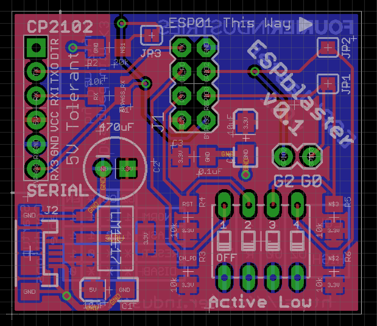
I designed a PCB called the ESPBlaster which you may be interested in. It takes a USB-TTL module on one side and has a socket for an ESP8266 module on the other to facilitate direct communications from your computer to the ESP8266 so you can set it to the correct baud rate so that you can interface it with an Arduino Uno, and contains a specially designed voltage regulator which does provides adequate current and decoupling.

ESPBlaster PCB

Your Answer

By clicking “Post Your Answer”, you agree to our terms of service and acknowledge you have read our privacy policy.

Not the answer you're looking for? Browse other questions tagged or ask your own question.