2

There are some discrepancies between what is read by the analog channel for a thermistor, ohms values directly obtained on the thermistor using an ohmmeter, and another digital temperature sensor.

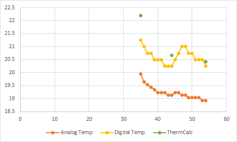
Figure 1: Left column (y axis) is degree Celcius; x axis is time (minutes). Orange is what was read by the analog channel (thermistor); in yellow the reading by a commercial digital sensor; and in green, manual readings of the thermistor using a ohm-meter.

A bit more context, we are building a simple system to read the temperature from a thermistor via an analog channel. Code algorithm is very similar to what is found here and the electronic layout inspired from here. When we ran into problems, we just went back to the working basics as instructed by those two above-mentioned references.

Pad resistor is 7K Ohms @ +/-1%, measured resistance was 6690 ohms Thermistor is 2252 Ohms @ 25 degree Celsius. Coefficients are as follow, coefficient were solved following a calibration in a thermal bath:

  • COEFF_A = 0.0014644
  • COEFF_B = 0.00023888
  • COEFF_C = 9.8996E-08

Specs from vendor are here (PDF) factory coefficient are about the same. I tried to calculate with either factory and in-house calibrated and there is a few thousandth of a degree of difference between the two - not enough yet to explain the current problem

While investigating I saw some sketch with the same resistance for pad resistor and thermistor, but have seen other differing thus assume this is not an issue.

To troubleshoot and isolate the origin of the discrepancies of the orange line VS other reading, we used

  1. other thermistors (every single one behave similarly as the orange line in the figure 1)
  2. other digital temperature sensors (every single one behave similarly as the yellow line in the figure 1)
  3. we try to put 2 analog thermistors and 2 digital temperature sensors on the same arduino - analog were consistant between each other (discrepancies) and the digital one were behaving as expected (correctly)
  4. we switched the pad resistor, no effect
  5. other arduinos (did not changed anything, every single one was repeatedly demonstrating the same behaviour )
  6. used the system in a temperature controlled room and the discrepancy was still present for the analog channel and absent for the digital sensor.

To be clear, green and yellow are what we think is the 'real' temperature; and the orange is the discrepancy. About 1 - 2 degree differences

We used the raw analog value read by the arduino as an input to manually feed and solve the Steinhart–Hart equation (like using IPYTHON and by hand) and output is the same as the orange line. Did the same with the thermistor obtained by the ohm-meter (Green dots on figure).

What should be investigated next to solve the discrepancy between what is read by the analogue channel connected to a thermistor and what the same thermistor provide to the ohm-meter?

Sketch follows

#define THERMISTORPIN_0 0               // analog pin 0 on the board 
#define SERIESRESISTOR_0 6990             // balance/pad resistor value (ohm)
#define THERMISTORNOMINAL 2252          // resistance at 25 degrees C
#define ZEROABS -273.15                 // zero Kelvin (Celsius)

#define COEFF_A 1.4644E-03          // Coefficient A for Steinhart-Hart eq.
#define COEFF_B 2.3888E-04          // Coefficient B for Steinhart-Hart eq.
#define COEFF_C 9.8996E-08          // Coefficient C for Steinhart-Hart eq.


void setup()
{
    Serial.begin(9600);  
}

void loop()
{
    float temp1;
    temp1 = Thermistor(analogRead(THERMISTORPIN_0),SERIESRESISTOR_0);
    Serial.println(temp1);
}

float Thermistor(int RawADC, long padResistance) {
  long Resistance;  
  float Temp; 
  Resistance = padResistance / ((1023.0 / RawADC) - 1); 
  Temp = log(Resistance); 
  Temp = 1 / (COEFF_A + (COEFF_B * Temp) + (COEFF_C * pow(Temp,3)));
  Temp += ZEROABS;                

  return Temp;                                      
}
18
  • 1
    try plotting VREF over same timeframe as read with a dmm, do you see distortion?
    – dandavis
    Commented Jul 13, 2017 at 17:41
  • 1
    What is the exact value of the 7k resistor ? Do you know the type of the resistor, to be able to find the A, B, C and β values in the datasheet. This online calculation might be useful: thinksrs.com/downloads/programs/Therm%20Calc/NTCCalibrator/… Please show your sketch.
    – Jot
    Commented Jul 13, 2017 at 20:53
  • 1
    You must be referencing VREF somewhere in order to calculate the resistance. After all, the resistance is measured by the voltage drop across it, and to convert the raw 0-1023 value of the ADC to a voltage you need to calculate it with respect to VREF. If you use the wrong value you will get the wrong result. 5V is not 4.91V.
    – Majenko
    Commented Jul 13, 2017 at 21:57
  • 1
    True, that is... Don't forget 10K should be 6690, of course...
    – Majenko
    Commented Jul 13, 2017 at 22:16
  • 1
    @Majenko, for a thermister plus resistor the VCC drops out the calculation. It is relative to VCC. In the calculation the 5.0 could be used, and the actual voltage may vary, it may be 4.0 or 5.5V, it does not matter. That's the beauty of a thermistor. However, the slightest deviation in the calculation and the curve will change. EtienneGodin, where is the sketch ? (it is 1024 ADC steps, not 1023).
    – Jot
    Commented Jul 14, 2017 at 1:28

3 Answers 3

4

One possibility that has not been mentioned yet: the issue may be the calibration of your ADC converter. Your code carries the implicit assumption that the voltage you measure is

V = Vref × RawADC ÷ 1023

The correct formula is

V = Vref × (RawADC + offset) ÷ scale

where offset is ideally 0 and scale is ideally 1024 (and not 1023, as you are assuming). Since you are looking at relatively small discrepancies, the “ideal ADC” assumption may not be a good enough. I have calibrated 3 Arduino ADCs and found offsets between 2.2 and 2.4, and scale factors between 1026.1 and 1026.3. Thus, if you have an accuracy issue, I recommend you calibrate your own ADC.

As a side note, you could expect slightly better accuracy if the thermistor and the resistor are closer in resistance. Right now you have a factor 3, which is not that bad, but you could use a 2.2 kΩ resistor, which is a very standard value.

1
  • I was able to figure out a function to calculate the offset - since there is an acceptable relation between measured and expected, whatever thermistors, Arduino boards, cables/wire or breadboards we are using. Your range suggestions for the offset helped to calibrate our curves.
    – marsisalie
    Commented Jun 13, 2019 at 11:48
3

So far I can see nothing wrong.

This is all about accuracy and being precise. That is how to deal with this problem. This is not a quick fix.
For example the resistor value has been: 10k, 7k, 6690 and 6990. That's too sloppy.
I think that you have not told us that the thermistor is at GND (I prefer it being at GND, that's good).

Test: At 25 °C the thermistor and resistor result in a ADC value of 249.5, and with that in the sketch the result is 25 °C. Very nice. Around 25 °C the sketch is accurate.

Instead of a short minimalistic calculation you could calculate everything. For example the resistance of the thermistor and the voltage at the analog pin. That would make it easer to check those values with a multimeter.
I prefer to let the Arduino do the calculation, and not trying to be smart and optimize something. Let the compiler to the optimizations.

We have to look further than the thermistor, the Arduino and the sketch.

  1. How long is a long wire ? What kind of cable ? Shielded cable ? Is one wire connected to GND ? and at the end is only the thermistor ? The GND is not used for something else ? Are the wires of the thermistor or the cable touching a metal object or water ? A multimeter is not connected to something, but an Arduino is connected via the usb to the computer and perhaps to earth ground. With a power supply, there is a small capacitive coupling to the mains. What happen if the Arduino is battery powered and not connected to something ?
  2. How well is the wire connected to the Arduino. Try to solder it if possible. If it is already soldered, was it a good weld ?
  3. What else is going on with the Arduino board ? It could be GND offset caused by something that pushes current through the GND. A LCD display with its background light connected in the wrong way could cause this. Is the thermistor connected via a breadboard, and there is something else on that breadboard ? Then you have almost certainly a DC offset.
  4. Could you try with another Arduino board and another computer ? Only the Arduino board, the thermistor + resistor and a USB cable to the computer. Without the long wires. Try a desktop computer, not a laptop (the usb 5V of a laptop could be less reliable). You are now caught in some kind of trap, and you get out by making a second test setup with a new set of components and not even using a single wire from the first setup.
  5. The NTC could cool down via the metal legs.
  6. Perhaps averaging a number of samples would help. When the final average calculation is done with float, you could even increase the resolution beyond 10 bits of the ADC.

For now, I think that the problem is between the thermistor and the microcontroller on the Arduino board. Could you try to eliminate any DC offset of the GND and be sure to isolate the thermistor (from metal objects and water)

0

there seems to be two problems:

1) calibration: the digital sensor / analog sensor may not be calibrated properly - this can account for the gap between the two curves.

2) response time: the digital sensor seems to react much faster than the analog sensor. that could be due to placement, physical attributes (smaller thermal mass for example), ...

Your Answer

By clicking “Post Your Answer”, you agree to our terms of service and acknowledge you have read our privacy policy.

Not the answer you're looking for? Browse other questions tagged or ask your own question.