4

There is tons of information on how IR remote controls work and how to use an Arduino to decode those signals and use any IR remote to suit your project. But I couldn't find much info about 2.4G RF remotes.

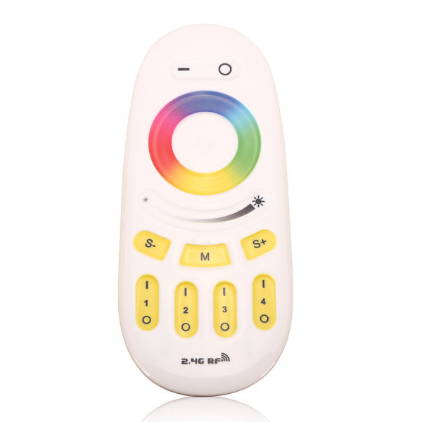
I want to control a string of addressable LEDs and cycle through different patterns using one of these 2.4G RF remotes

2.4G RF RGB LED controller

Is it possible to use these remotes with Arduino? If yes, how can I read the signals and assign tasks to different buttons on the remote?

1
  • 2
    First step would be to open it up, and see what chip is inside. Just the 2.4GHz isn't saying very much, as 2.4Ghz is also used by WiFi, Bluetooth, some Zigbee. All different kinds of encodings and protocols.
    – Gerben
    Commented Jun 10, 2017 at 15:31

3 Answers 3

2

The usual approach for 2.4 GHz is to open the product, identify the radio chip, and use a USB logic analyzer on the SPI bus that usually connects it to the MCU to capture the configuration and data traffic, and figure out what the configuration register accesses mean from the radio chip data sheet.

The occasional appearance of combined MCU/radio parts prevents that approach, but often that is only used on one end of the link and the other will still have a distinct MCU and radio with an SPI bus in between.

This is heavily practiced in the radio control community, as people want to use their nice transmitters to fly cheap toys. And there is code out there to transmit compatibly with some of the odder chips like the X297, using more common ones like the NRF24L01 or its workalikes from Beken, etc.

A key advantage of SPI sniffing versus over-the-air sniffing is that the usually implemented channel-hopping doesn't mean you loose the signal ever time it moves to a new channel - and you actually get to the see the frequency registers being written. To capture a hopping scheme over the air, you would need something more like a spectrum analyzer to figure out the sequence, and then have software track the signal while you attempt to figure out the data. However, a remote which only sends occasional button presses may not use hopping in the way something sending data continuously (like an R/C set, or possibly a keyboard/mouse) would.

1

I was having same issue and at the end of the day I have made it working. For the communication I have used openmili library (project started by Henryk Plötz who has reverse engineered protocol for communication of these remotes). This didn't work with new remotes as they have changed couple of things:

  • Listens on a different channelset (this was true of different bulb types among the old bulbs too). The new bulbs use channels 8, 39, and 70.
  • Different PL1167 syncword. It uses 0x7236 , 0x1809 .
  • Packets have 9 bytes instead of 7.
  • Packets are scrambled. The same command can look completely different.

(information taken from Chris Mullins blog)

Confirmation of these info I have found in ESP8266 Milight hub project where I have found config for remotes (https://github.com/sidoh/esp8266_milight_hub/blob/master/lib/Radio/MiLightRadioConfig.cpp)

In my case I was using rgb+cct remote so it tells me that I should use 0x7236, 0x1809 as syncwords, packet length 9 and channels 8, 39, 70.

Applying those changes I was able to get data from the remote. One more usefull link.

0

If it is based on the nRF24L01+ (or the nRF31512C SoC, which is a combined MCU and nRF24L01+ in one chip, and used in most wireless mice and keyboards) then it may be possible to sniff the signal. If not, you're probably not going to have much luck.

You'd be better off trying to hack the existing receiver that is paired with the remote to get usable signals out of it.

Your Answer

By clicking “Post Your Answer”, you agree to our terms of service and acknowledge you have read our privacy policy.

Not the answer you're looking for? Browse other questions tagged or ask your own question.