I have tried to follow along/reproduce the results from several sources for emulating the Nikon infrared remote trigger:
- Adafruit Guide
- DIY Nikon ML-L3 IR Wireless Remote Hack with Arduino UNO
- Teardown and Project: Clone Nikon ML-L3 IR Remote and Emulation
- Teach you how to DIY Nikon ML-L3 infrared remote control did not read yet
- Arduino wireless remote for Nikon DSLR
- Arduino Nikon Infrared command code
- Arduino – IR remote/ intervalometer for Nikon D80 DSLR
I can read the signal from my remote trigger, but I cannot reproduce it with my Arduino setup. The signal I can receive (w/ TSOP38238 receiver diode) matches all of the signals given by the links above (there is some expected variance in pulse durations).
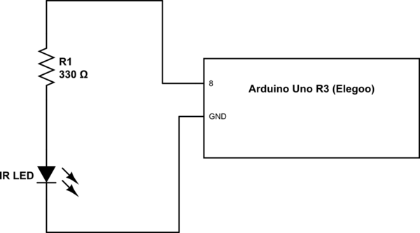
I don't think my hardware is at fault:
- TSOP38238 receives @ 950 nm
- my IR LED is 940-950 nm per datasheet
- my IR LED works (I can see it emitting when I point it at my phone camera)

simulate this circuit – Schematic created using CircuitLab
My Code:
I have tried the code given in the links above, most don't use Port Manipulation and instead trial-and-error the delay durations to account for the overhead in Arduino functions. I have experimented with different values of the wait variable (8-13 microseconds) but have not gotten it working so far. I prefer to have my code versatile like this (no hard coded durations) so I can use it with other remotes in the future.
uint16_t Signal[] = [2050, 27800, 430, 1650, 430, 3650, 430, 65000]; // ON & OFF pulse durations (microseconds)
uint8_t wait = 13; // duration (microseconds) between pin state changes

// the setup function runs once when you press reset or power the board
void setup() {
    DDRB = B00000001; // set digital pin 8 to output
    PORTB = B00000000; // set digital pin 8 LOW
    Serial.begin(9600); // start serial monitor
}

// the loop function runs over and over again forever
void loop() {
    delay(1500); // wait a bit between sending signal
    sendSignal();
    sendSignal();
    // send signal twice, this is what the actual remote does
    Serial.println("Signal sent"); // message saying signal was sent
}

// function that sends the signal
void sendSignal(void) {
    for (int i = 0; i < sizeof(Signal)/sizeof(Signal[0]); i++) { // for each element in Signal array
        if (i%2 > 0) { // odd numbered index, is an OFF pulse
            PORTB = B00000000; // set digital pin 8 LOW
            delayMicroseconds(Signal[i]); // delay for OFF pulse duration
        } else { // even numbered index (including i=0), is an ON pulse, 38 kHz (26.3 usec period), 50% duty cycle
            unsigned long currentTime = micros(); // get current time
            while (micros() - currentTime < (unsigned long)Signal[i]) { // while still in ON pulse duration
                PORTB = B00000001; // set digital pin 8 HIGH
                delayMicroseconds(wait); // leave ON for time
                PORTB = B00000000; // set digital pin 8 LOW
                delayMicroseconds(wait); // leave OFF for time
            }
        }
    }
}
I hold my camera in direct line of sight of the LED (not blocking the receiver on the camera) from distances of ~2in to ~3ft away without success.
Has anyone tried this before? Is there a mistake in my approach or code?
