0

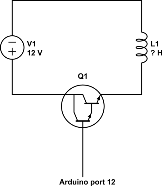
I have magnet hooked up to my arduino with a Darlington Transistor, like this:

enter image description here

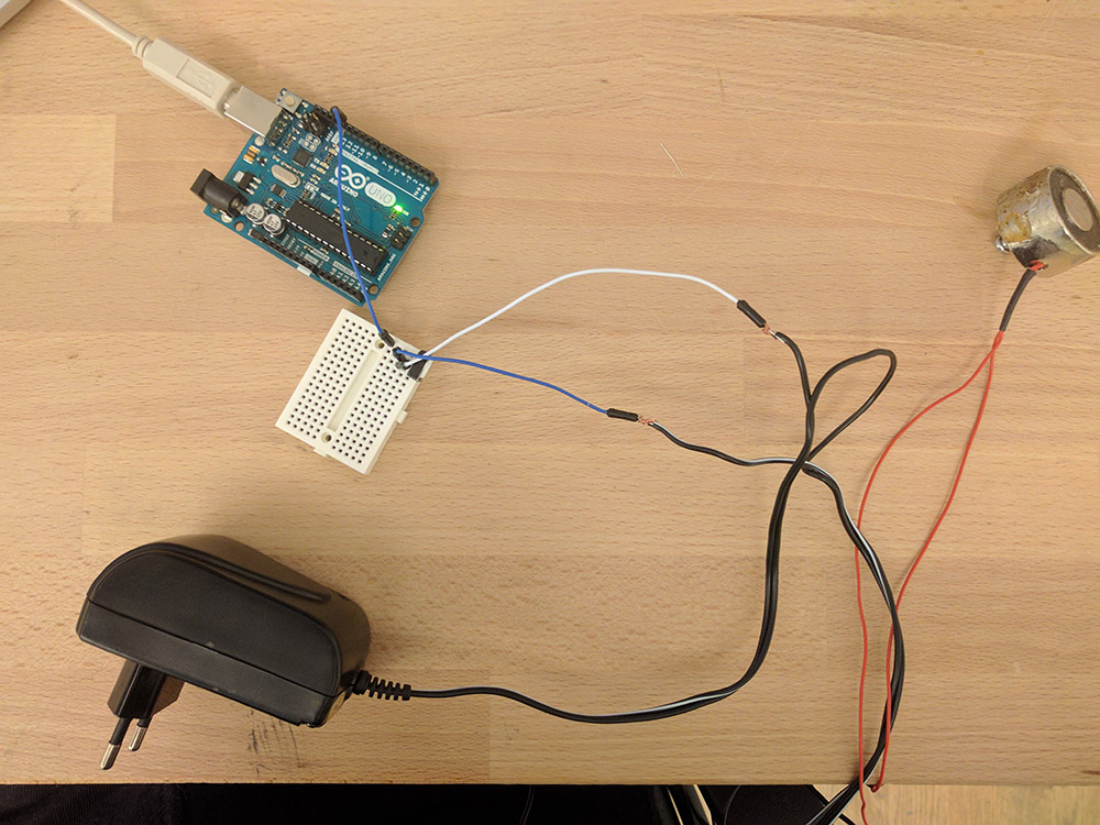
The powersource is a 12V adapterenter image description here

I'm pretty new to electronics but i'm told that the transistor won't work unless the ground on the arduino is the same as the ground on the external source. How do I do this in practice? Should I run a wire from the ardunio-ground to the negative pole on the powersource? How do I tell which one is the negative one?

1
  • Your first question about this subject is from Aug 2016. You really need start with a Electricity 101 course for your own safety.
    – user31481
    Commented Sep 9, 2017 at 8:27

3 Answers 3

2

Ground is usually (though not always, but in your case it is) the point of lowest potential in a circuit. In your circuit that is the "negative" connection of the power supply. Note that the "negative" isn't actually "negative", it is zero volts when measured from the reference point of itself.

So yes, you need to know which is the "negative" connection and connect that to ground on the Arduino.

Since you already have it wired up the negative is the one which connects to the emitter of your transistor. If you don't know which that is and you just randomly connected a random wire to a random pin then you need to investigate your power supply.

The simplest way is with a Digital MultiMeter (one of the most basic items you need to own if you are working with electronics - if you don't have one then go and buy one immediately). Set it to DC Volts in the right range then connect the two probes (correctly inserted into the right sockets on the DMM) to the power supply's output connections. If the voltage reads positive then the black probe is connected to negative. If it reads a negative value then the red probe is connected to negative.

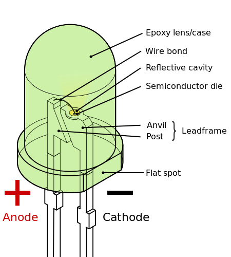
If you cannot get a DMM but you have an LED (note: a bulb will not work) and a suitable resistor (say 2.2K) you can connect the resistor in series with the LED then connect the two to the power supply. The cathode of the LED (the pin with the flat side on the case) connects to negative. Connect the power both ways round. The way round that it lights the LED is the correct way round, and you know that the connection that goes to the cathode (flat side of the lip round the bottom of the LED) is the negative.
1
  • “Since you already have it wired up the negative is the one which connects to the emitter of your transistor” – What's that mean? Anyhow, for a grounded-emitter low-side switch, either the battery or the transistor in the diagram in the question is backwards, an issue you might address with a correct diagram in your answer. Commented Nov 1, 2016 at 3:01
2

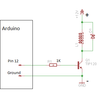
Majenko explained how to figure out what is what. I'm just repeating the shematics again with "additional" description:

enter image description here

Current limiting resistor R1 is REQUIRED, if you don't want to destroy Arduino output by over current.

About using the LED to test your power source polarity:

enter image description here

And again, current limiting resistor is required, or you'll burn it. As Majenko stated, it should be about 2k2.

2

I would be careful about "ground loops" when using two supplies connected to the mains electricity. You may get strange results. If you are using a lap top then maybe disconnect it from the charger while the PSU is plugged in the wall. Or use a battery for your coil. Or power the Arduino from a power bank. Or get a 12v USB adaptor and power the arduino from the 12v supply. Add and LED for debugging while connected to the computer. Then disconnect from the computer and plug in the 12v supply.

1
  • very useful info!
    – Himmators
    Commented Oct 31, 2016 at 13:03

Not the answer you're looking for? Browse other questions tagged or ask your own question.