Q: how far can you go with 5v and still get signal back?
That depends on two main factors:
- The gauge of the wire
- The noise in the environment
Assuming a low-noise (where noise is negligible) environment, we will first look at the wire.
All wire has an inherent resistance to it. The thicker the wire, the lower the resistance. This table has good information about the resistance of different gauges of wire: http://www.powerstream.com/Wire_Size.htm
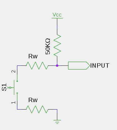
Given a typical arrangement where the internal pullup resistor of the Arduino's IO pin is used to create an "active low" arrangement (pinMode(x, INPUT_PULLUP) the equivalent circuit can be seen as this:

Given that the "Input Logic Low" (VIL) level of an input pin (according to the ATMega328P Datasheet (Table 30-1) is 0.3Vcc, and Vcc is 5V, the input low level would therefore be 1.5V. The voltage present at the IO pin has to be below 1.5V in order for the input to be seen as a LOW.
The circuit, when the button is pressed, can be simplified to this:

That is a simple voltage divider. The formula for calculating Vout is (R2/(R1+R2))*Vin. We know that the Vout limit is 1.5, and Vin is 5V. Also that R1 is approximately 50KΩ (very approximately). So we can rearrange the formula to:
R2 = R1(1/((Vin/Vout)-1))
Substituting our known values we have:
R2 = 50,000 × ( 1 / ((5 / 1.5) - 1)) = 21428.57Ω
So the total resistance of the wire permissible is around 20KΩ assuming the internal pullup resistor is 50KΩ (note: it could be as low as 10KΩ or as much as 70KΩ).
Divide that value by 2, since the wire has to run twice the distance (once there and once back again) and you get a total resistance of around 10KΩ for one leg of the journey.
Now assume a wire gauge of 24AWG. That has a resistance of 84.1976Ω/km. So we can work out that 10,000 / 84.1976 = 118.77km.
So with 24AWG wire you could theoretically have your button about 100km away from the Arduino and just about have it still register properly.
But of course that's with no noise, and there will be noise - especially over that kind of distance.
The noise will basically make the voltage seen at the input vary randomly around the theoretical value. Those wires act like great big antennae, and they pick up all sorts of stray EMI. The longer the wires the more noise there will be, and consequently the lower the voltage you will need to aim for (or higher voltage if using a pull-down arrangement - just turn the whole thing upside down) to keep the logic level below (or above) the right threshold value.
Q: is their away to boost the signal?
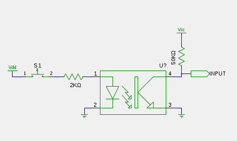
Yes, you can use a higher voltage. There is nothing to say that you have to interface your button directly with the Arduino. There are many ways of having your button switch a higher voltage on and off and use that to trigger the Arduino. The simplest (and also the safest) may be to use an opto-coupler. Use your button(s) to switch a 12V power supply on and off, and that then passes through a suitable resistor to power the LED in the opto-coupler. That then switches on the built-in transistor to turn on the IO pin.

Another option may be to use a reliable communication bus with a small microcontroller at each stop-button point (maybe something like RS-485), though that may be overkill for this kind of application.


