1

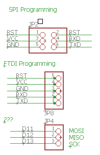
I took a look at a barebones Arduino schematic. It had three different ways of programming the chip. enter image description here

The first interface is for programming through SPI (For example with "Pocket AVR Programmer", or "USBTinyISP").

The second interface is for programming through an FTDI to USB module.

What is the third programming interface? It only has MOSI, MISO and SCK.

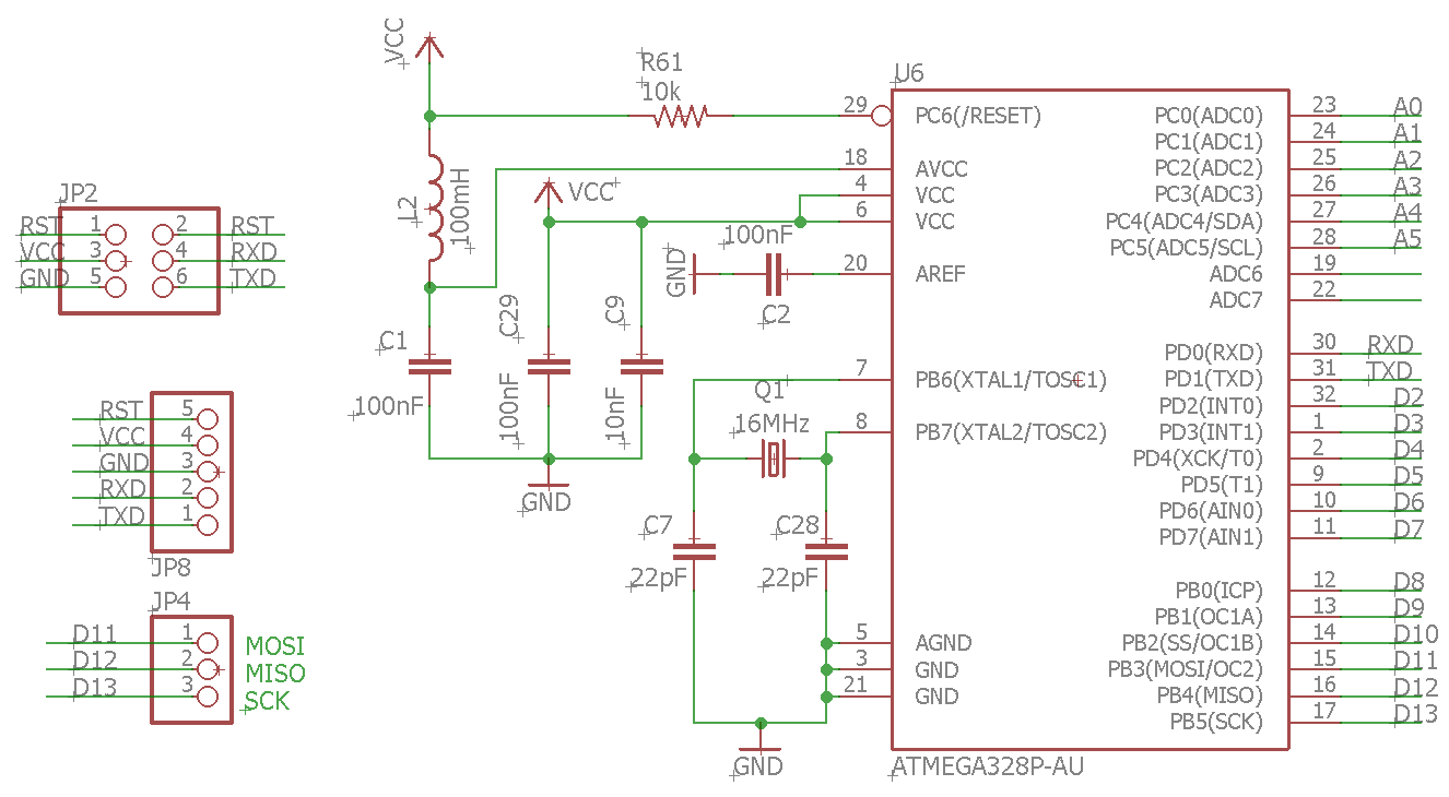
EDIT: This is a picture of the full schematic. Unfortunately, I could not find the link from which I downloaded it. I am sure it was from Github though.

enter image description here

3
  • Please include/link the full schematics. From what you posted, I can only say that the first two pin headers both connect to the same UART pins (RXD/TXD, making both the same UART programming interface, just with differently-shaped pin headers) and the third connects to the SPI pins of the chip -- but I would think that that pin header is there to connect SPI periphery/sensors, not for ICSP (in-circuit serial programming).
    – orithena
    Commented Sep 6, 2022 at 14:40
  • @orithena I updated the question with the full schematic. Commented Sep 6, 2022 at 14:55
  • Okay, that clears up the level of "barebone-ness" :)
    – orithena
    Commented Sep 6, 2022 at 15:06

2 Answers 2

2

JP2 and JP8 are both serial pin headers suitable for programming -- they connect to the same pins of the chip: RXD, TXD and RST. This is programming via UART: A bootloader software (which has to be "pre-burnt" in the chip's flash memory) is the first thing that is run after a reset (RST) signal. It waits a little moment for data to arrive on RXD. If data arrives, the bootloader goes into programming mode: the data is written to flash memory, making it the firmware to be executed after the next RST. (If no data arrives: well, then the firmware that already is there is executed.)

Programming the chip via JP4 would use "hardware-supported" programming interface via SPI, recognizeable by the pins MISO, MOSI and SCK. That is the only way to get the first bootloader into the flash memory. It also provides you with a way to flash and re-flash a firmware without a pre-burnt bootloader (making the bootloader space available to your firmware). That method is described in the ATmega328P datasheet, chapter 27.8 and is the primary method employed by "ISP programmer boards". You could use those from the Arduino IDE using the menu option "Upload using programmer".

If this "barebone Arduino" circuit is meant to use an ATmega328P with the Arduino bootloader, however, I would assume that JP4 is meant to provide a pin header for some SPI sensor module (even though you could program and even un-brick the chip using this interface).

NB: "FTDI" is a red herring here. One of the most-used ISP programmer boards employs an chip made by FTDI, so you could call this method "programming via FTDI" ... but a specific USB-to-Serial cable using an chip made by FTDI and an 1x5 pin header is also called an "FTDI cable". (For a while, FTDI made the best USB-to-Serial chips. Clones just did not work that reliable. Today, CH340G and CP2104 are reliable enough for hobby projects, but somehow, "FTDI" stuck as a name.)
3
  • Just adding docs.platformio.org/en/latest/platforms/… for the platformio...
    – Tomas
    Commented Sep 7, 2022 at 13:26
  • Thank you! I have one more question though. You said that JP4 is used for programming via an external programmer. However, I use the first pinout (JP2) with an external programmer (Sparkfun's Pocket AVR Programmer) that uses SPI communication protocol as an ISP (In System Programmer). So is there another protocol/interface being used with JP4? Commented Sep 12, 2022 at 12:34
  • @user1584421 That does not match the schematics you posted. JP2 and JP8 have the pins RXD und TXD, which points to an UART interface. JP4 has MISO, MOSI and SCK, which points to SPI interface. So either the schematics do not match the circuit you got in front of you, or you did use JP4 but remember using JP2, or the PocketAVR programmer has a method of detecting whether it should use UART or SPI that I don't know of (and is not described in its feature list).
    – orithena
    Commented Sep 13, 2022 at 10:26
1

The 2x2 pin JP2 is connected to the Atmel 16U2 or 32U2 processor (whichever the manufacturer used) which provides the USB I/O interface to/from the Atmel 328p, the one we usually consider to be the Uno's processor. When pins are actually installed on that pad, jumpers may be placed across either or both pairs to connect the xxU2's pin-4 to pin-6, and/or pin-5 to pin-7, which connect to that processor's interrupts (numbered the same as those pins).

My searches have not yielded any answer to the question of why it was provided, other than to suggest that they may have been intended for a feature that was never implemented. You can see JP2 and its connections to the xxU2 processor in the center of this schematic.

Update:

I was looking at the 3-pin connector(?) marked '???' in your question, and JP4 on the schematic in your update. Since your schematic does not show the xxU2 chip, and the connections of '???' are marked D11, D12, and D13, I'm going to guess instead that these are either auxilliary pins to access the 328's SPI interface, or is showing half of the ICSP hardware programming interface (the 3x2 pin block just above the '328 on the schematic I linked).

1
  • Thank you very much! I updated the question with the full schematic, if that is of any help to you. Commented Sep 6, 2022 at 14:56

Your Answer

By clicking “Post Your Answer”, you agree to our terms of service and acknowledge you have read our privacy policy.

Not the answer you're looking for? Browse other questions tagged or ask your own question.