I am using ESP-12e as a controller for my garden lights. I am using pins 1 (TX), 3 (RX) and 5 as an analog output (PWM signal with mosfets) for three separate light sets. ESP is powered on when wall switch is turned on (wall switch turns on power adapter). When I turn the switch on, for short period of time lights connected to pin 1 and 3 work at full power and after that they are set according to PWM signal. Lights on pin 5 works just as expected. I am not using Serial communication, just elegantOTA library for OTA updates and async web server. Is it possible to somehow disable RX/TX functionality at all/before they are set to high, or I am forced to solder lights on pins 1 and 3 to another ones? I tried some software tricks I found online, but without success.
2 Answers
I am not using Serial communication,
You might not be, but the bootloader sure is.
Is it possible to somehow disable RX/TX functionality at all/before they are set to high
No. It's hard coded in ROM. There's nothing you can do.
or I am forced to solder lights on pins 1 and 3 to another ones?
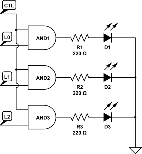
You could use one IO pin to control a buffer the other IO pins. Something like an AND gate (74HC08) would do the job:

simulate this circuit – Schematic created using CircuitLab
Only when CTL is HIGH will the L0-L2 signals be mirrored on the outputs to the LEDs. That way you ignore whatever is going on with those pins until you actively drive the CTL signal high. Choose one pin that has no boot noise for CTL and the other pins then don't matter.
For more detail on what pins do what at boot time read this.
-
Thanks. I was hoping I could solve this problem only with software because of difficult access to esp-12. I understand the way with AND gate, but probably simpler way for me is to cut off cables from RX/TX and solder to more appropriate pins. Commented Oct 17, 2020 at 21:14
-
After some digging I realized, that esp-12 has only two pins (4 and 5) which are perfectly suitable for my job (no high state on boot), so as I need three pins, your AND buffer technique is best option. Commented Oct 18, 2020 at 8:45
-
This is why most WiFi lights that use the ESP8266 (or ESP8285 most commonly) use a PWM LED driver chip, like the MY9231. Offload the LED control to something else and don't worry about what happens at boot on the ESP8266.– MajenkoCommented Oct 18, 2020 at 11:06
According to this reference, GPIOs 1 and 3 have dedicated behaviour during boot (debug output or pulled high) which can not be disabled in your sketch. You have to either choose different pins or implement an additional circuitry.
-
Thanks. I was hoping I could solve this problem only with software because of difficult access to esp-12. I did not give enough time to the selection of pins, but at least, I learned something new. Commented Oct 17, 2020 at 21:19
