2

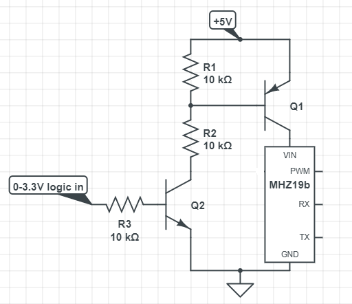
I've been trying to turn off an MHZ19B (datasheet and teardown photos: revspace.nl/MH-Z19B). I've used an Arduino, NPN, PNP transistors and mosfets as well as the diagram below for connecting the sensor to an ESP32. In all cases, PWM communication works great! I can power off the sensor, turn it back on, and values derived from PWM communication are as expected. However when I connect the Rx and Tx lines (to software serial Tx and Rx pins respectively on Uno pins A0 A1 or ESP32 pins 32 33) they spit out gibberish and the PWM signal also suffers hiccups.

Otherwise, without any kind of logic power control, the MHZ19B works great and can communicate with anything via UART, even my PC usb port via FTDI.

I added resistors to the Rx and Tx lines so the voltage on them doesn't exceed Vcc. I tried 1n4007 diodes (they're the only ones I have; no Schottky diodes either). I tried an NPN equivalent optocoupler. I also tried powering the sensor from my breadboard. I don't own an oscilloscope :(

My High School teacher said to just use PWM, but as I searched for a solution to this error, I noticed hundreds of others have this exact same problem with all sorts of different sensors and loads with ICs; no one has come up with a general solution.

I've been obsessing with this for weeks and if anyone can help or can recommend a book about sensor schematics I would really appreciate it. Thanks! MHZ19B and ESP32 attempt at deep sleep
4
  • 4
    You need to disconnect the serial, before turn of the power of the module. What I think happens is that the TX pin on MCU (RX on the MHZ19b) is HIGH when it isn't sending it anything. So you get 3.3-5V going into the MHZ19b that's powered down (which is bad). A lot of chips have clamping diodes on there input pins. So you are essentially powering the chip via the TX pin. The TX pin can supply enough power to the chip, with cause weird things to happen. For example gibberish UART data.
    – Gerben
    Commented Sep 28, 2020 at 18:44
  • PS R2 looks weird to me. I think you need to move it the the horizontal section. Otherwise you only get 2.5V at the base of Q1, when Q2 is turned on.
    – Gerben
    Commented Sep 28, 2020 at 18:46
  • It seems software serial doesn't have a function to "disconnect". A workaround is to set the TX pin to an INPUT, and to LOW (pinmode(txPin, INPUT); digitalWrite(txPin, LOW);). Then make sure you don't call any mySerial.print commands while power is off. Then when powering on the chip, do the reverse (pinmode(txPin, OUTPUT); digitalWrite(txPin, HIGH);
    – Gerben
    Commented Sep 28, 2020 at 18:55
  • @Gerben R2 is okay. The base of Q1 will not go more than one diode drop below 5V regardless of R2 value.
    – Wirewrap
    Commented Sep 29, 2020 at 20:14

2 Answers 2

1

Just guessing but I suggest you use a level translator. Also when you power off the sensor the serial output should go to ground disabling that channel. Check your voltages and put a bypass cap on the transistor for the sensor. You can use a simple P channel Logic Level fet,only a 50 ohm resistor in the gate to prevent oscillation. Your output will now be active low instead of active high. If you stay with transistors make R2 & R3 510 ohm so you have enough drive for the transistor and be sure it is NOT a darlington device, if it is you will not have enough voltage for the sensor.

2
  • I think the sensor has a built in level translator since the datasheet says it can use 3.3V or 5V logic. I tried to add a 100uF capacitor between +5V and VIN, but I don't know if it did anything. The sensor itself has 12 internal capacitors (or maybe 16 cause there is a silkscreen labeled C16) connected to ground. Is there an alternative to using transistors? How do some sensors just go to sleep and use virtually no power?
    – Constantin
    Commented Oct 4, 2020 at 19:08
  • That capacitor will only decrease your noise immunity and make it more susceptible to line noise. That is not enough information, those are operating voltages, not input voltages. 3.3V and 5V logic are not compatible with each other even though both can operate on both voltages. If you look at the input structure you will see the threshold changes with the supply voltage. Thresholds are roughly 40% and 60% of VCC. That is only really valid if the sun comes up on the east side of the moon on February 33d. As far as something to read I would suggest you start with something in basic electronics.
    – Gil
    Commented Oct 5, 2020 at 23:58
1

When troubleshooting a problem like this, try 'cutting the world in half' before doing anything else. In this case, replace the entire circuit with a manual switch (or a wire) and manually power and de-power the sensor. If you still have the problem, then the circuit is irrelevant to the solution. If the problem goes away, then the circuit IS the problem.

Once this experiment has been performed, then 'cut the world in half' again, working on the 'half' that is the problem. Repeat until only one component is left.

4
  • Thanks! Yeah I did that from the start. I didn't even use a microcontroller to power on and off the sensor. I just had the Rx and Tx ports connected to my computer to monitor values, and powered the sensor from a breadboard power supply connected to a wall outlet. I managed to get 4.6V @50 milliamps, using NPN or PNP based circuits, which is within spec. But the sensor never wanted to work. I suspect the internal capacitors are doing something. I would try to add a capacitor inline with the circuit but I don't know how. I think the sensor needs to draw 150 mA at the start to turn on its logic.
    – Constantin
    Commented Sep 30, 2020 at 17:26
  • Glad you tried the simple route first, but it sounds like your setup still had problems. You can get 5V power supplies from MeanWell power supplies that are cheap and reliable.
    – starship15
    Commented Sep 30, 2020 at 22:55
  • The sensor works. I ran it 24/7 for 3 months with a read every 60 seconds. If it didn't work I never would have made a post about transistors. Also why would I need a 100W power supply for a project designed to use an ordinary 5V 1A cell phone charger?
    – Constantin
    Commented Oct 2, 2020 at 17:50
  • No no - not 100W or even close. For instance,meanwell.com/webapp/product/search.aspx?prod=GS05U-USB is a 5W (1.0A at 5V) wall plug with a USB connector - perfect for supplying reliable power to a range of projects. Cut off the end of a USB cable, and wire the +/- wires to a barrel plug that fits the Arduino, and 'Bob's your Uncle' (saying from "The world's fastest Indian" movie).
    – starship15
    Commented Oct 2, 2020 at 23:13

Your Answer

By clicking “Post Your Answer”, you agree to our terms of service and acknowledge you have read our privacy policy.

Not the answer you're looking for? Browse other questions tagged or ask your own question.