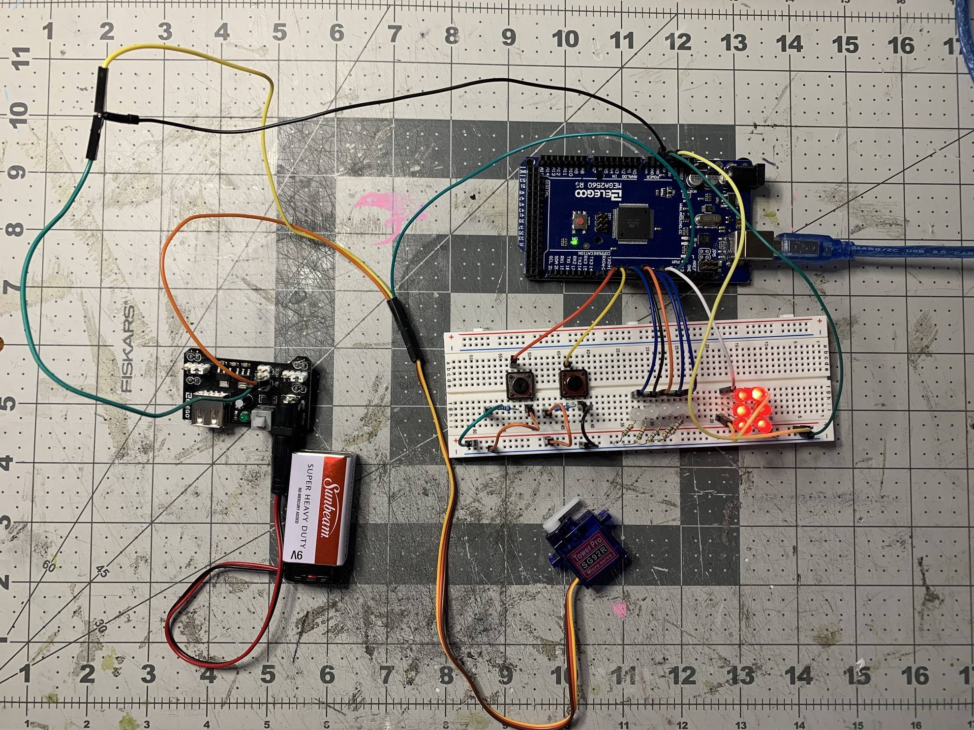
 The image is as clear as I can make it.
Here are the basics of my problem. My program is meant to make 6 red LED lights in sequence fade in and out, toggle 5 white LED's on and off with a button, and make a servo rotate from 90 to 15 degrees on a button press, and revert to 0 degrees when the button is no longer pressed.
All of my code has compiled correctly, the LED's do what they are supposed to do, but the servo is acting strange. At first, it would move fine but then after a few button presses it would kind of spaz out and glitch back to place instead of smoothly move, which will not work for my purposes. After even more time, the servo stopped working at all. I looked around and found some answers saying to route it through an alternative power source, but I did that with the power module that came with my kit and it still refuses to move. I swapped it out with a different servo and that one won't work either, which makes me wonder if my wiring is incorrect - and yet the motor is on and makes vibrations, instead of moving, so I know power is getting through. In addition, the onboard LED's on the mega2560 are turning on and off in response to my button, so I know that's wired in correctly as well! So why won't the servo move, and why won't it respond to my button presses?
Basically, using a 3.3V - 5.0 volt Elegoo power module, how do I correctly wire the servo to only draw power from the 9v battery I attach to said module? I've seen people saying something about putting the grounds of the board and the module together but I don't know how to do that and I'm getting frustrated looking all over the internet trying to find out how so I figured I would just ask a question.
Wiring details:
The 5 white LED's are in parallel, and the red LED's are in series; they are all powered by the arduino's 5V power source, and wired into the arduino GND pin. Servo is connected by to pin 10, and the ground and power are both routed through the 5V power module which is attached to a 9V battery. The light on the module is on, and I have used the included jumpers to make sure I'm using the 5V source and not the 3.3V one.
Here is my code:
#include <Servo.h>
Servo servo1;
//------------------------
// White LED's:
int wL1 = 3;
int wL2 = 4;
int wL3 = 5;
int wL4 = 6;
int wL5 = 7;
//------------------------
// Red LED's:
int rL1 = 8;
//------------------------
// Buttons:
int wLbutton = 2;
int wLreading;
int wL1state = HIGH;
int wL2state = HIGH;
int wL3state = HIGH;
int wL4state = HIGH;
int wL5state = HIGH;
int wLprevious = LOW;

int servoButton = 1;
int servoState = false;
int servoReading;
int servoPrevious = LOW;
//--------------------------
// Fading:
int brightness = 0;
int fade = 1;
//--------------------------
// Delays:
long time = 0;
long time2 = 0;
long debounce = 100;

unsigned long previousMillis = 0;
const long interval = 1000;
//--------------------------


// Setup ======================================================================================================================================

void setup()
{
  pinMode(wL1,OUTPUT);          // White LED's
  pinMode(wL2,OUTPUT);
  pinMode(wL3,OUTPUT);
  pinMode(wL4,OUTPUT);
  pinMode(wL5,OUTPUT);

  pinMode(rL1,OUTPUT);          // Red LED's

  pinMode(wLbutton, INPUT);     // Buttons
  pinMode(servoButton, INPUT);

  servo1.attach(10);
  servo1.write(90);             // Servo

  if (wL1state = HIGH)
{
  wL1state = LOW;                                                              // Set the state of the all White LED buttons to low at the beginning of the circuit (this doesnt run after the first time).
  wL2state = LOW;
  wL3state = LOW;
  wL4state = LOW;
  wL5state = LOW;
}
}


// Loop =========================================================================================================================================

void loop() {

// White LED Button -----------------------------------------------------------------------------------------------------------------------------


wLreading = digitalRead(wLbutton);                                             // Read the state of the White LED Button

if (wLreading == HIGH && wLprevious == LOW && millis() - time > debounce)      // If the button is different state from last reading and ignores noise
{
  if (wL1state == HIGH)                                                        // If the current button state of the White LED button is high
  {
  wL1state = LOW;                                                              // Set the state of the all White LED buttons to low
  wL2state = LOW;
  wL3state = LOW;
  wL4state = LOW;
  wL5state = LOW;
  }
  else {
    wL1state = HIGH;                                                           // Otherwise, set the state of the White LED button to high
  }
  time = millis();                                                             // Set the last time the button was pressed to the current time
}

digitalWrite(wL1,wL1state);
digitalWrite(wL2,wL1state);
digitalWrite(wL3,wL1state);
digitalWrite(wL4,wL1state);
digitalWrite(wL5,wL1state);

wLprevious = wLreading;                                                        // Set the previous reading of the White LED button to current reading

// Servo Button ----------------------------------------------------------------------------------------------------------------------------------

servoState = digitalRead(servoButton);

if (servoState == HIGH)
  {
    servo1.write(75);
  }
  else
  {
    servo1.write(0);
  }

// Red LED'S breathing ----------------------------------------------------------------------------------------------------------------------------

 analogWrite(rL1,brightness);                                                 // Write the set brightness to the red LED
 brightness = brightness + fade;                                              // Set new brightness to brightness value + fade value

 if (brightness <= 0 || brightness >=255)                                     // If brightness is less than 0 or more than 255
  {
  fade = -fade;                                                               // Negate the fade value, reversing the direction of the fade
  }
  delay(10);                                                                  // Wait a short delay to see the fade
}```
