0

Getting an audio signal from a 3.5mm jack amplified (non-inverted) and fed into analog in pin on a Mega 2560. I am having problems using a potentiometer as a variable resistor to adjust gain. I'm also getting a lot of noise (+/-10 units on the 0-1023 scale)

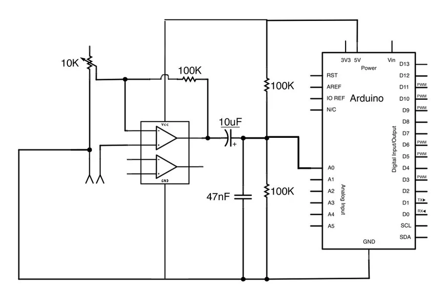
Circuit: - The audio is from a mono 3.5mm jack, playing from my laptop (with audio split to my speakers). - Audio goes through an op amp TL071, single sourced shared with arduino 5V - The potentiometer is wired with 2 pins as a variable resistor. The pins are connected to ground and the inverting input (VCC-) - Output signal from the op-amp is biased by 2.5V and seems to work fine.

modified circuit

I'm closely following the instructions here (https://www.instructables.com/id/Arduino-Audio-Input/) but with a TL071 op amp as a single sourced from the Arduino 5V power supply.

The potentiometer doesn't seem to make much difference; I can even unplug it and I still get some readings on A0. I'm misunderstanding how to 'rewire' the op-amp for a single supply, but I can't figure out what else I can do.

1
  • I've also tried moving the variable resistor to bridge the output and inverting input (swap with the 100k resistor)
    – What The J
    Commented Dec 31, 2019 at 7:01

2 Answers 2

0

The TLO series don't work with 5v supply. They have also a reversal phase : that meens, when used in follower, it's output will go high when intut is lower than 3v... One can use an old LM324 or LM358, but output is not going up to VCC... OPA140 is a correct choice. Also, may be a link capacitor of 100µF between input and potentiometer is necessary : this avoids amplification of DC, gives a centered output, and will reduce noise due to DC paht in potentiometer.

1
  • What I read from other posts was that the TL0 series is ok to use with 5V because I'm only trying to amplify a very small audio input.
    – What The J
    Commented Dec 31, 2019 at 11:17
0

In case anyone is looking for a solution, I followed the TL071 manual (texas instruments) for an op-amp instead of using the diagram posted above. That signal then links into a bias.

The noise was coming from having 5V shared with the LED lights (WS2812B). Once I put them on a different circuit (shared ground) it was ok.

Your Answer

By clicking “Post Your Answer”, you agree to our terms of service and acknowledge you have read our privacy policy.

Not the answer you're looking for? Browse other questions tagged or ask your own question.