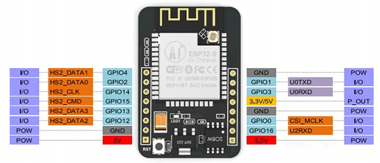
I have tried all the GPIO pins listed here: I am following this tutorial to save a picture using the ESP32 cam board. I am trying to add a PIR sensor.
https://randomnerdtutorials.com/esp32-cam-take-photo-save-microsd-card/
whenever I try to use any pins to enable wake on external pin high, there is an error either because of interruption with the camera initiation or sd card.
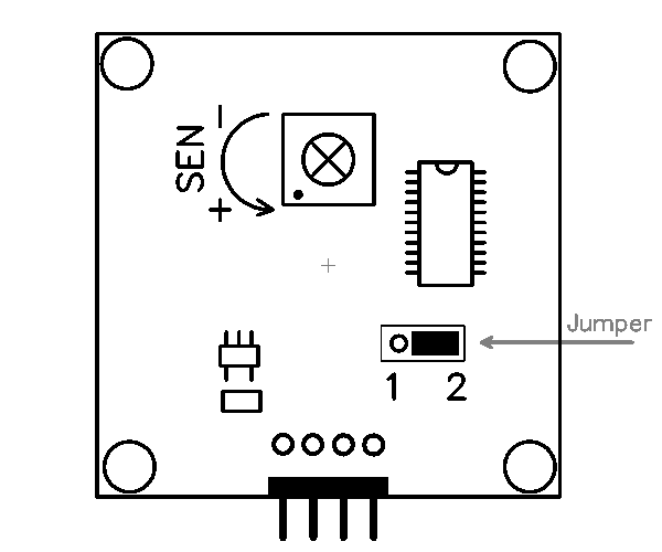
here is my PIR sensor
https://www.robotshop.com/en/wide-angle-pir-motion-sensor.html?gclid=EAIaIQobChMI0Y7QuaOA4wIVl_5kCh3zYA4OEAQYASABEgJFPvD_BwE here is the code I am using
    /*********
      Rui Santos
      Complete project details at https://RandomNerdTutorials.com/esp32-cam-    take-photo-save-microsd-card

      IMPORTANT!!!
       - Select Board "ESP32 Wrover Module"
      - Select the Partion Scheme "Huge APP (3MB No OTA)
    - GPIO 0 must be connected to GND to upload a sketch
    - After connecting GPIO 0 to GND, press the ESP32-CAM on-board RESET  button to put your board in flashing mode

   Permission is hereby granted, free of charge, to any person obtaining a copy
  of this software and associated documentation files.
  The above copyright notice and this permission notice shall be included in all
  copies or substantial portions of the Software.
*********/

 #include "esp_camera.h"
 #include "esp_timer.h"
 #include "img_converters.h"
 #include "Arduino.h"
 #include "fb_gfx.h"
 #include "fd_forward.h"
 #include "fr_forward.h"
 #include "FS.h"                // SD Card ESP32
 #include "SD_MMC.h"            // SD Card ESP32
 #include "soc/soc.h"           // Disable brownour problems
 #include "soc/rtc_cntl_reg.h"  // Disable brownour problems
 #include "dl_lib.h"
 #include "driver/rtc_io.h"
 #include <EEPROM.h>            // read and write from flash memory


    // define the number of bytes you want to access
     #define EEPROM_SIZE 1

     // Pin definition for CAMERA_MODEL_AI_THINKER
     #define PWDN_GPIO_NUM     32
     #define RESET_GPIO_NUM    -1
     #define XCLK_GPIO_NUM      0
     #define SIOD_GPIO_NUM     26
     #define SIOC_GPIO_NUM     27

     #define Y9_GPIO_NUM       35
     #define Y8_GPIO_NUM       34
     #define Y7_GPIO_NUM       39
     #define Y6_GPIO_NUM       36
     #define Y5_GPIO_NUM       21
     #define Y4_GPIO_NUM       19
     #define Y3_GPIO_NUM       18
     #define Y2_GPIO_NUM        5
     #define VSYNC_GPIO_NUM    25
     #define HREF_GPIO_NUM     23
     #define PCLK_GPIO_NUM     22

     int pictureNumber = 0;

     void setup() {
       WRITE_PERI_REG(RTC_CNTL_BROWN_OUT_REG, 0); //disable brownout detector

       Serial.begin(115200);
       //Serial.setDebugOutput(true);
       //Serial.println();

       camera_config_t config;
       config.ledc_channel = LEDC_CHANNEL_0;
       config.ledc_timer = LEDC_TIMER_0;
       config.pin_d0 = Y2_GPIO_NUM;
       config.pin_d1 = Y3_GPIO_NUM;
       config.pin_d2 = Y4_GPIO_NUM;
       config.pin_d3 = Y5_GPIO_NUM;
       config.pin_d4 = Y6_GPIO_NUM;
       config.pin_d5 = Y7_GPIO_NUM;
       config.pin_d6 = Y8_GPIO_NUM;
       config.pin_d7 = Y9_GPIO_NUM;
       config.pin_xclk = XCLK_GPIO_NUM;
       config.pin_pclk = PCLK_GPIO_NUM;
       config.pin_vsync = VSYNC_GPIO_NUM;
       config.pin_href = HREF_GPIO_NUM;
       config.pin_sscb_sda = SIOD_GPIO_NUM;
       config.pin_sscb_scl = SIOC_GPIO_NUM;
       config.pin_pwdn = PWDN_GPIO_NUM;
       config.pin_reset = RESET_GPIO_NUM;
       config.xclk_freq_hz = 20000000;
       config.pixel_format = PIXFORMAT_JPEG;

       if(psramFound()){
         config.frame_size = FRAMESIZE_UXGA; // FRAMESIZE_ +  QVGA|CIF|VGA|SVGA|XGA|SXGA|UXGA
        config.jpeg_quality = 10;
        config.fb_count = 2;
      } else {
        config.frame_size = FRAMESIZE_SVGA;
        config.jpeg_quality = 12;
        config.fb_count = 1;
      }

      // Init Camera
      esp_err_t err = esp_camera_init(&config);
      if (err != ESP_OK) {
        Serial.printf("Camera init failed with error 0x%x", err);
        return;
      }

      //Serial.println("Starting SD Card");
      if(!SD_MMC.begin()){
        Serial.println("SD Card Mount Failed");
        return;
      }

      uint8_t cardType = SD_MMC.cardType();
      if(cardType == CARD_NONE){
        Serial.println("No SD Card attached");
        return;
      }

      camera_fb_t * fb = NULL;

      // Take Picture with Camera
      fb = esp_camera_fb_get();
      if(!fb) {
        Serial.println("Camera capture failed");
        return;
      }
      // initialize EEPROM with predefined size
      EEPROM.begin(EEPROM_SIZE);
      pictureNumber = EEPROM.read(0) + 1;

      // Path where new picture will be saved in SD Card
      String path = "/picture" + String(pictureNumber) +".jpg";

      fs::FS &fs = SD_MMC;
      Serial.printf("Picture file name: %s\n", path.c_str());

      File file = fs.open(path.c_str(), FILE_WRITE);
      if(!file){
        Serial.println("Failed to open file in writing mode");
      }
      else {
        file.write(fb->buf, fb->len); // payload (image), payload length
        Serial.printf("Saved file to path: %s\n", path.c_str());
        EEPROM.write(0, pictureNumber);
        EEPROM.commit();
      }
      file.close();

      // Turns off the ESP32-CAM white on-board LED (flash) connected to GPIO 4
      pinMode(4, OUTPUT);
      digitalWrite(4, LOW);
      rtc_gpio_hold_en(GPIO_NUM_4);

      delay(2000);
      Serial.println("Going to sleep now");
      delay(2000);
      esp_deep_sleep_start();
      Serial.println("This will never be printed");
    }

    void loop() {

    }
This is the thing I am trying to add. but no matter which pins i chose there are errors. I can add the error if that would be helpful.
esp_sleep_enable_ext0_wakeup(GPIO_NUM_X, level)
