1

I have NodeMCU ESP8266N Lolin V3, my 5V relay is powered from Vin of the NodeMCU. The NodeMCU is powered from 5V USB.

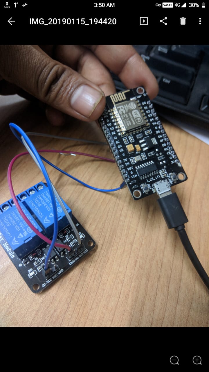
My difficulty is when I measure voltage between Vin & GND, it is of 1.9V, but supposed to be around 5V as it is directly attached with usb 5V supply. Actually my relay is not working with the power tapped from Vin, but relay's led & NodeMCU led are blinking but relay coil does not trip. Please confirm is my NodeMCU having problems as voltage between vin & GND read 1.9V. https://drive.google.com/file/d/1Z6jYX4sCLmRxnWbtBYZCNW6LpckokaC9/view?usp=drivesdk enter image description here
10
  • 1
    Vin ... the in is the clue - I wouldn't use it as a Vout Commented Feb 1, 2019 at 1:38
  • possibly duplicate of arduino.stackexchange.com/questions/51873/… - there is an answer there that suggests using the VV pin for your requirements ... however, don't be surprised if your setup is unstable, due to the power requirements of the NodeMCU and the Relay Commented Feb 1, 2019 at 1:45
  • 2
    Vin does not provide enough current to operate a relay ..... Vin is an input to a voltage regulator .... the voltage regulator cannot be used in reverse
    – jsotola
    Commented Feb 1, 2019 at 4:54
  • 1
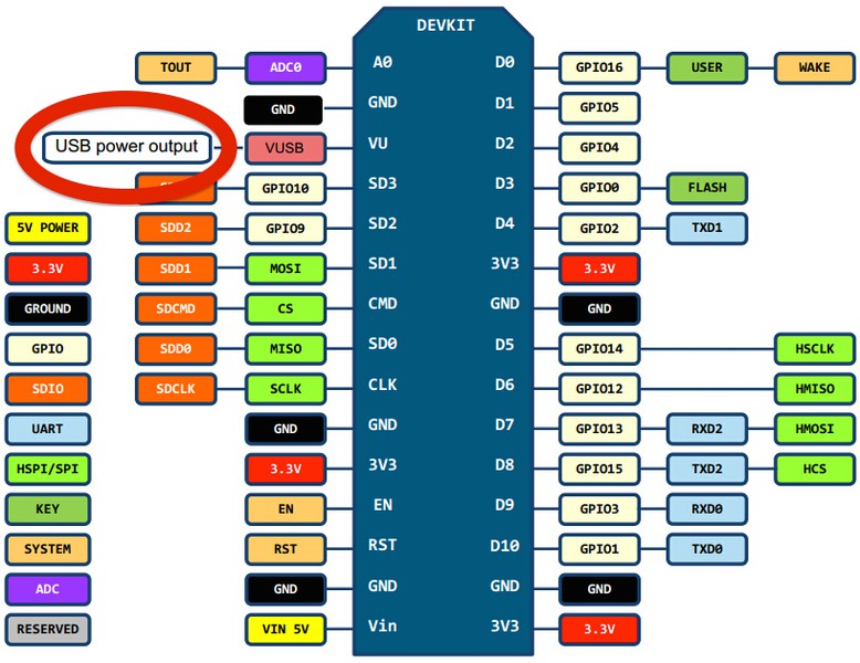
    @SumitRoy - you have a Lolin V3 board - I can tell that because below A0 you have GND and VV instead of Rsv and Rsv - VV is "V USB Power output" ... use that with a decent USB power supply (not from a PC as that probably wont supply enough current) ... as I mentioned 5 hours ago ... USE VV Commented Feb 1, 2019 at 7:53
  • 1
    Sorry ... it's VU ... not VV ... I'm old and my back is blind and my eyes are bent :p Commented Feb 1, 2019 at 8:15

2 Answers 2

3

The voltage on Vin when you power that board thru USB is not relevant ... Vin is not the pin you are looking for

You clearly have a Lolin NodeMCU (V3) board - the existence of Gnd and VU (looks like VV in your picture!!) between A0 and S3 pins indicates that

In documentaion easily found by searching for Lolin V3 pinout - VU is described a USB power output

Lolin v3 pinout

Use this pin to connect to JD-VCC on the relays

I've just now successfully done this with a 4 relay board

I would connect (nodemcu -> relay)

  • 3V3 to VCC
  • VU to JD-VCC
  • Gnd to Gnd
  • Dn to INm - i.e. choose a D pin on the NodeMCU and connect to an IN pin on the relay
10
  • Thanks a lot to give me solution from your precious time, sir, i have tried this solution in the morning, but fail, could you pls provide some link or email so that i can post the video i recorded, sir just for sake of confirmation, i just want to mention that i gave power to relay by doing as follows , VV of nodmcu to JD- VCC of relay, G of nodmcu to left-hand side GND of relay , and D4 of nodmcu to in1 of relay, pls tell am i correctly doing connection, thanks in advance
    – Sumit Roy
    Commented Feb 1, 2019 at 13:31
  • You need to connect the 3V pin to the VCC pin on the relay board. JD-VCC is just for the relay coils. Vcc is used for the optocouplers which currently don't have power at all, looking at the picture.
    – Gerben
    Commented Feb 1, 2019 at 13:45
  • I think the grey wire in the picture probably goes to vcc ... no wait ... that picture is hard to see ... the other issue the OP has is the lack of VCC as you poinbt3ed out @Gerben - that other VCC can be 3v3 (I know, because that's how I connected mine) Commented Feb 1, 2019 at 13:49
  • Gray goes to IN2. Most of these boards have a jumper between VCC and JD-VCC. But you probably don't want that here. The opto-isolators led could light up if the pin is set to HIGH (3.3V) on the ESP. So the led will see 1.7V across it.
    – Gerben
    Commented Feb 1, 2019 at 13:57
0

It is hard to tell from your pictures but I don't think you have your relay connected properly.

Some problems i see:

  • Your esp8266n seems to be a 3 Volt device; it has 3V output pins
  • Vin usually feeds a regulator; the +V rail is usually after it
  • Your relay needs 5V but you only have 3V for power and signal

You will need a level shifter, and another powersupply to run your relay. You should be able to put 5v into Vin on your ESP and have it be powered, then you will need a level shifter to connect to the IN1 or IN2 of the realy so that you can control it with 3v. And the relay Vcc and GND also connected to the same power supply.

2
  • Sir, could you please get to know that just connecting relay Vcc with 3.3V Vcc of esp8266 , lot of youtube video demonstrates that relay of 5v works even on 3.3 V. Just Google it pls. There is no external power supply required other than tapping power from esp8266 to power relay. Pls let me know what's the voltage between Vin & ground is it 1.9V!
    – Sumit Roy
    Commented Feb 1, 2019 at 5:58
  • the voltage on your particular board is what you measure @SumitRoy - when powered thru USB, mine is 4.74 volts with nothing connected to it - but none of my nodemcu boards are Lolin brand, and neither have a pin labelled VV which I suggested you use 5 hours ago - did you try that at all? Commented Feb 1, 2019 at 7:42

Your Answer

By clicking “Post Your Answer”, you agree to our terms of service and acknowledge you have read our privacy policy.

Not the answer you're looking for? Browse other questions tagged or ask your own question.