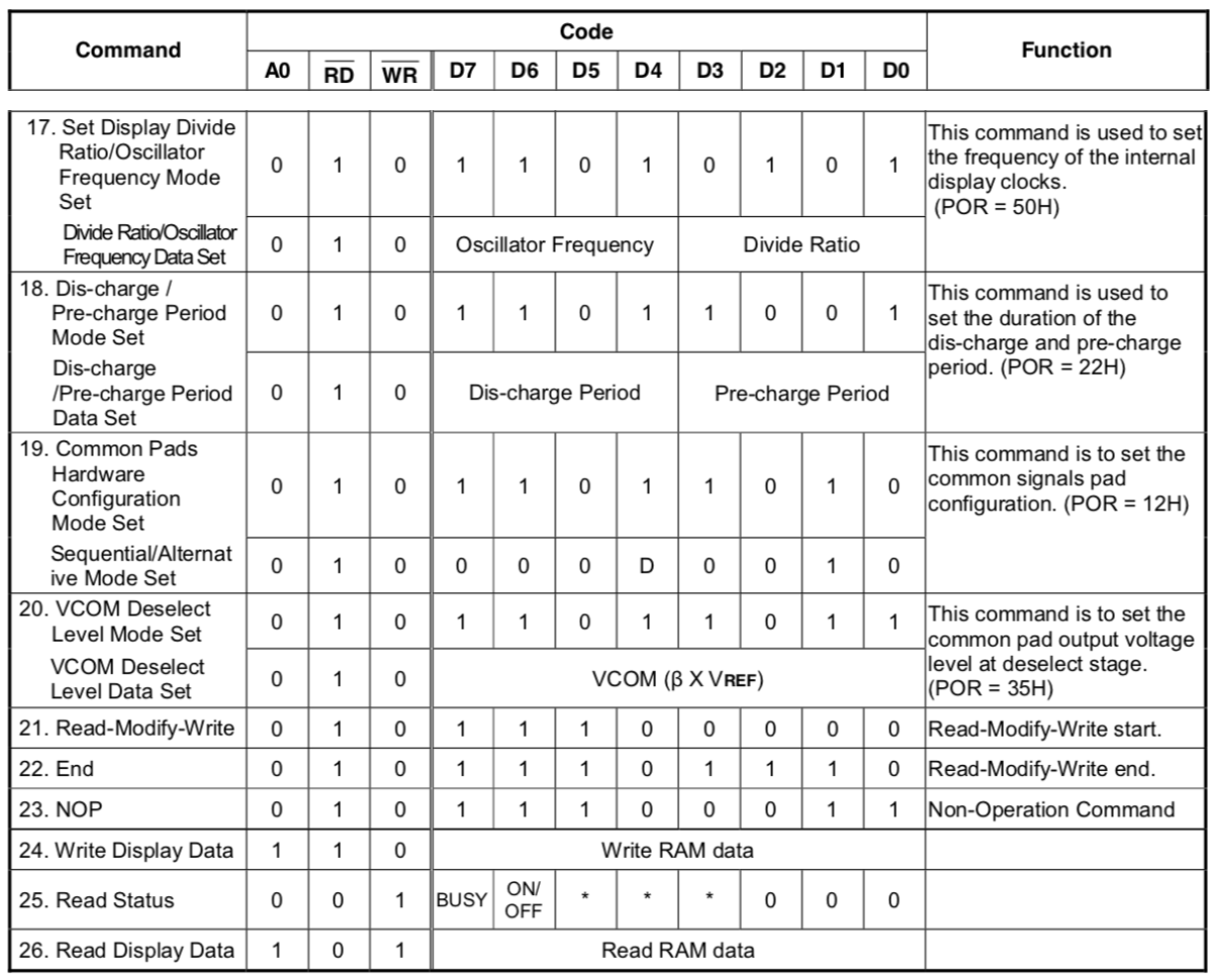
Summary: I'm having trouble with writing a program to get RAM data from an SH1106 OLED controller via i2c. In the first part of the question I've written the assumptions I've made to get informations I couldn't find in the datasheet, in the second part I've posted a program which should read that data but doesn't (obviously, since I'm writing here...).
I'm working on a program to control an SH1106 OLED display. I read the datasheet to find out how to send commands to it and it works, I can write to my display.
Now in the datasheet there is one thing I don't understand: how can I read the RAM?
Consider the picture below, taken from the command table at pages 30 and 31 of the SH1106 datasheet; the last line is the one about reading RAM.
This chip can be connected to a microcontroller through different interfaces: 6800 and 8800 8-bit parallel, 3 and 4 wire SPI and i2c. Since I'm using SPI I don't have any A0, RD or WR pin, and I didn't found anywhere in the datasheet a "translation" of the boolean value given to those signals in the command table to some i2c signal. I assume that WR corresponds with the lsb of the i2c address, since it is 0 for writing and 1 for reading. And my assumption seems to be true since I can read the status (line 25).
Then I assumed that A0 should match DC (Data/Command, see second screenshot), a bit of the Control byte. The control byte is a byte that has to be sent before each byte or group of bytes to tell the chip how to interpret it (command or data). But I tried to send it before an i2c reading with different values and I always get the status byte (never the RAM data).
How could I read the memory of an SH1106 chip through i2c? The datasheet doesn't states that it is impossible (neither that it is possible...), maybe I simply can't?
Command table
 (I removed lines 1-16, which contain commands like those at lines 17-23)
Control byte

EDIT
Here is the shortest working program I could write which shows the problem (i.e. which contains my implementation errors). I tested it on an Arduino UNO.
#define ADDR  0x78


void i2c_start() {
  TWCR = (1 << TWINT) | (1 << TWSTA) | (1 << TWEN);
  while (!(TWCR & (1 << TWINT)));
}

void i2c_stop() {
  TWCR = (1 << TWINT) | (1 << TWEN) | (1 << TWSTO);
}

void i2c_send(uint8_t data) {
  TWDR = data;
  TWCR = (1 << TWINT) | (1 << TWEN);
  while (!(TWCR & (1 << TWINT)));

}

uint8_t i2c_read(bool isLastByte) {

  if (isLastByte) TWCR = (1 << TWINT) | (1 << TWEN);
  else TWCR = (1 << TWEA) | (1 << TWINT) | (1 << TWEN);
  while (!(TWCR & (1 << TWINT)));
  return TWDR;
}


void display_init() {
  i2c_start();
  i2c_send(ADDR);
  i2c_send(0x00); //................ control byte
  i2c_send(0xAE); //................ displayOff
  i2c_send(0x8D); //................   *
  i2c_send(0xD5); i2c_send(0x80); // clockFrequency
  i2c_send(0x32); //................ pumpVoltage0123
  i2c_send(0xA1); //................ segmentRemap
  i2c_send(0xC8); //................ flipVertically
  i2c_send(0xDA); i2c_send(0x12); // comConfiguration
  i2c_send(0xA8); i2c_send(0x3F); // multiplex
  i2c_send(0xD3); i2c_send(0x3F); // displayOffest
  i2c_send(0x10); i2c_send(0x00); // columnAddr
  i2c_send(0x40); //................ startLine
  i2c_send(0xB0); //................ pageAddr
  i2c_send(0xAF); //................ displayOn
  i2c_stop();
}


void setup() {

  // Initialization
  Serial.begin(115200);
  display_init();

  // Request RAM data
  i2c_start();
  i2c_send(ADDR);
  i2c_send(0x80); //   control byte
  i2c_send(0xB0); // page address
  i2c_send(0x80); //   control byte
  i2c_send(0x10); // column address high
  i2c_send(0x80); //   control byte
  i2c_send(0x00); // column address low
  i2c_send(0x40); //   control byte
  i2c_send(0xE3); // nop
  i2c_stop();

  // get RAM data
  uint8_t a[10];
  i2c_start();
  i2c_send(ADDR + 1);
  for (int i = 0; i < 9; i++) a[i] = i2c_read(false);
  a[9] = i2c_read(false);
  i2c_stop();

  // print results
  for (int i = 0; i < 10; i++) {
    Serial.print("0x");
    Serial.println(a[i], HEX);
  }

}

void loop() {}
I've tried as many possibilities as I could imagine in the // Request RAM data section. To avoid confusion I leave only the posted one to your kind analysis, but of course if someone would like to see them just write it in a comment and I'll post all the (unsuccessful) test I have made.
The output on the serial monitor is always a list of 0x3s.
I've not reduced the initialisation routine I use in my code because maybe the issue comes from there. BTW, I have no idea about what the i2c_send(0x8D); //................ * line does, I've added it because all the others SH1106 libraries I found had it, but I didn't found it in my datasheet. Maybe there are multiple versions of the chip or of the datasheet?
