2

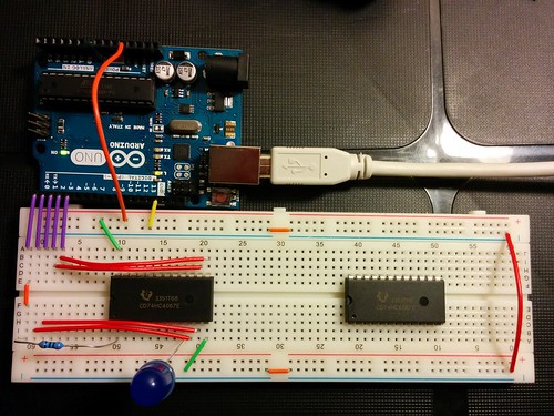
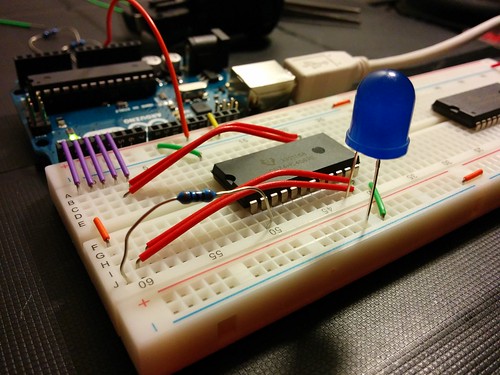
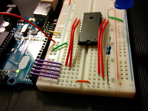
I am testing a 74HC4067E MUX setup with my Arduino Uno which I would like to use to selectively light up many LEDs, one at a time. For this first test, I am using a modified version of the blink tutorial. Essentially, I am setting the 4 control pins to digital LOW and setting the input to HIGH, through a resistor appropriate for my LED. I am also providing 5V to the Vcc pin on the MUX. I don't really know why I am doing this, but it seems to work. Here is my code:

int led_input = 0;
int led_ctrl_1 = 1;
int led_ctrl_2 = 2;
int led_ctrl_3 = 3;
int led_ctrl_4 = 4;

void setup() {                
    pinMode(led_input, OUTPUT);  
    pinMode(led_ctrl_1, OUTPUT);  
    pinMode(led_ctrl_2, OUTPUT);  
    pinMode(led_ctrl_3, OUTPUT);  
    pinMode(led_ctrl_4, OUTPUT);  
}

void loop() {
    // control signal
    digitalWrite(led_ctrl_1, LOW);
    digitalWrite(led_ctrl_2, LOW);
    digitalWrite(led_ctrl_3, LOW);
    digitalWrite(led_ctrl_4, LOW);

    // input signal
    digitalWrite(led_input, HIGH);
    delay(500);
    digitalWrite(led_input, LOW);
    delay(500);
}

I know, the code could be more efficient.

The blue LED is hooked up to I0 and blinks as it should. The problem comes when I try to change the control pin values. When I change it to, say 6...

// control signal
digitalWrite(led_ctrl_1, LOW);
digitalWrite(led_ctrl_2, HIGH);
digitalWrite(led_ctrl_3, HIGH);
digitalWrite(led_ctrl_4, LOW);

... and I move my LED to I6, I get no blink. I've tested all the pins and it doesn't seem like there is a signal coming from any of them. I assume that I am using the chip wrong, but I'm not sure how. Pictures of my setup follow... any help is greatly appreciated!

  • Arduino pin 0 maps to chip pin 1 (through resistor) as input.
  • Arduino pins 1-4 map to chip pins 10, 11, 14, and 13 in that order.
  • I have a 5V going to chip pin 24.
  • The LED is connected long leg to chip pin 9 in the images, the grounded.

IMG_20140622_221940

IMG_20140622_221954

IMG_20140622_222012

2
  • 1
    Pins 1 & 2 are connected to the breadboard but NOT connected to the IC, as you forgot to put a wire from E to F on the breadboard for these pins, they are thus not connected to your IC.
    – jfpoilpret
    Commented Jun 23, 2014 at 4:33
  • Good eye! I will give it a run tonight. This is the second time you have solved one of my questions. I wish you would post these as answers so that I can give you credit!
    – Rip Leeb
    Commented Jun 23, 2014 at 13:16

1 Answer 1

2

Pin 15 on that MUX is the enable pin, you need to tie it to ground. Otherwise, it's just floating, and it only would have worked by accident.

Also, you state:

I am also providing 5V to the Vcc pin on the MUX. I don't really know why I am doing this, but it seems to work.

The chip needs power to work. The Vcc pin is where you give it the +5V power. Without that, it might still work, but only by accident and depending on the inputs on the other pins.

4
  • I've heard a few things about floating pins and grounding them for stability's sake. Any suggested reading to help me fully understand the subject?
    – Rip Leeb
    Commented Jun 23, 2014 at 18:43
  • 1
    @Nate It's not just stability, but the enable pin 15 is an input to the logic in the chip. The output depends on the state of all inputs as defined by the truth table in the data sheet. The enable input is pretty important and its state is undefined if you don't connect an input wire to it. If the enable input is undefined, then it follows that the output is undefined. Commented Jun 23, 2014 at 19:09
  • 1
    @Nate The exception is inputs that are marked with an X in the truth table (which indicate a "don't care" input). Commented Jun 23, 2014 at 19:10
  • It worked! It worked sporadically after I actually connected pins 10 and 11 as jfpoilpret suggested, but it works consistently with the enable pin grounded. In fact, this fixes another issue I was having - I had been needing to disconnect the 5V supply line from the arduino board in order to upload code to it. Now, that is not needed. Thanks!
    – Rip Leeb
    Commented Jun 23, 2014 at 23:20

Your Answer

By clicking “Post Your Answer”, you agree to our terms of service and acknowledge you have read our privacy policy.

Not the answer you're looking for? Browse other questions tagged or ask your own question.