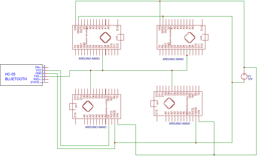
TL;DR: Multiple Arduinos listening to a single serial rail are burning out my HC-05's TX pin. Arduinos are leaking voltage onto the signal rail. How do I stop, or isolate that to keep from burning out Bluetooth TX pin?
I'm trying to build an LED-based track light that uses an HC-05 to communicate with up to 8 Arduinos to control up to 16 LEDs total. Each Arduino can only control 2 LEDs because of the shape and form factor of the project.
The track has 3 rails, 12V, Ground and Signal and all Arduinos share the same rails. Hopefully the schematic below does a good job explaining it.
On to my issue. Initially, I was getting almost 5V from my pin 7 (SoftwareSerial pin) on the Arduinos, which was quietly ruining the TX pin on my HC-05. I lowered that to about 1v after using pinMode(bluetoothTx, INPUT);, which is good but not good enough. That voltage starts to add up as I add more and more Arduinos to the overall setup.
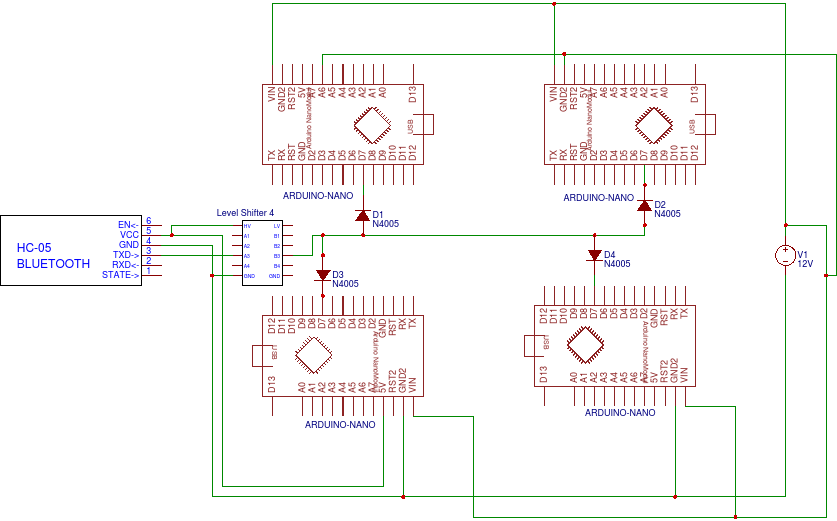
My solution in theory is to add diodes to pin 7 on the Arduinos, so they can't put voltage on the signal rail. This drops the voltage by 0.7v from what I've read, which most likely is why the Arduinos aren't reading a signal now, because that drops it below the logic level required, since the HC-05 is only putting out 3v3. So I think to add a level shifter on the HC-05 to pump up the signal to 5v, then the diode's voltage drop shouldn't matter right? See schematic below.
My solution seems unnecessarily convoluted and I don't even know if it would work. The more I read without bouncing the information off of others, the more confused I am becoming. Now after reformatting this post for an hour, I am thinking about a decoupling capacitor between the pin and ground... Will that have the effect I am looking for?
I also looked into using a pulldown resistor, but from everything I've seen (and from the first electronics course I've taken), it seems like an inappropriate solution. The examples I've seen usually use a switch, which makes sense, but for my application I am protecting the TX pin on my HC-05, so I think it would not give the effect I am looking for (tapping the line in between resistor and pin would not isolate the voltage, tapping in after the resistor would short the signal to ground).
I'm including my code for completeness, but the schematic is where I think I need help. Could someone point me in the right direction, I don't mind working for my answers but I've been going solo at this for over a month now, and I'm not even at the point in my education where we've covered much logic yet. I'm reaching a little here.
#include <EEPROM.h>
#include <SoftwareSerial.h>

byte address = 1; //change this to change light address
byte lightno = (address + 1); // variable to print light number
int addressShifter= ((address)*500); //This number will be subtracted from input
int bluetoothTx = 7; //btTX to pin 7 //input from HC-05
int bluetoothRx = 8; //btRX to pin 8 //not used
int led1 = 3; // the PWM pin LED1 is attached to
int led2 = 5; // the PWM pin LED2 is attached to
int brightness1 = EEPROM.read(0); //Recalling previous setting
int brightness2 = EEPROM.read(1); //Recalling previous setting
int thismodMin = (0 + addressShifter); //min two-byte looked for
int thismodMax = (499 + addressShifter); //max two-byte looked for

SoftwareSerial bluetooth(bluetoothTx, bluetoothRx); //naming it bluetooth and assigning it to the variables shown

void setup() {
    pinMode(led1, OUTPUT); // sets the pin as output
    pinMode(led2, OUTPUT); // sets the pin as output
    pinMode(bluetoothTx, INPUT); // sets the pin as input
    //Setup usb serial connection to computer
    Serial.begin(9600);
    //Setup Bluetooth serial connection to android
    bluetooth.begin(9600);
    analogWrite(led1, brightness1); //Set Led brightness from stored values
    analogWrite(led2, brightness2); //Set Led brightness from stored values
    Serial.println("SETUP COMPLETE, I am Light #"); //Identify self
    Serial.println(lightno);
    Serial.println("expecting Min "); //Min value listened for
    Serial.println(thismodMin);
    Serial.println("expecting Max "); //Max value listened for
    Serial.println(thismodMax);
}

void loop() {
    //---------Serial Communication---------
    if(bluetooth.available()>= 2) {
        unsigned int blu1 = bluetooth.read();
        unsigned int blu2 = bluetooth.read();
        unsigned int blueinput = (blu2 *256) + blu1;
        //I don't know why any of the above is neccesary but it will not read correctly without this conversion
        //Serial.println("blueinput = "); Not used
        //Serial.println(blueinput);  Not used
        if (((blueinput) >= (thismodMin)) && ((blueinput) < (thismodMax))){
            //If this blueinput is within this modules adress range, convert signal to PWM
            int thisMod = ((blueinput) - (addressShifter));
            //Convert blueinput to a value this module will work with (0-500)
            //-----------Lights---------
            if (((thisMod) >= 0) && ((thisMod) < 100)){ //0=off 1-100=on-Bright
                brightness1 = ((thisMod)*2.55); //converts percentage brightness to PWM value
                analogWrite(led1, brightness1); //apply brightness
                //      Serial.println("brightness1: "); //diagnostics
                //      Serial.println(brightness1); //diagnostics
                delay(10);
            } else if (((thisMod) >= 101) && ((thisMod) < 201)){ //101=off 102-201=on-Bright
                brightness2 = (((thisMod)-101)*2.55); //subtract starting value and then convert percentage brightness to PWM value
                analogWrite(led2, brightness2); //apply brightness
                //      Serial.println("brightness2: "); //diagnostics
                //      Serial.println(brightness2); //diagnostics
                delay(10);
            } else if ((thisMod) == (399)){ //if specific code recieved
                EEPROM.write(0, brightness1); //store brightness setting for light 1
                Serial.println("Epprom1 written");
            } else if ((thisMod) == (424)){
                EEPROM.write(1, brightness2); //store brightness setting for light 2
                Serial.println("Epprom2 written");
            } else{}
        }
    }
}


