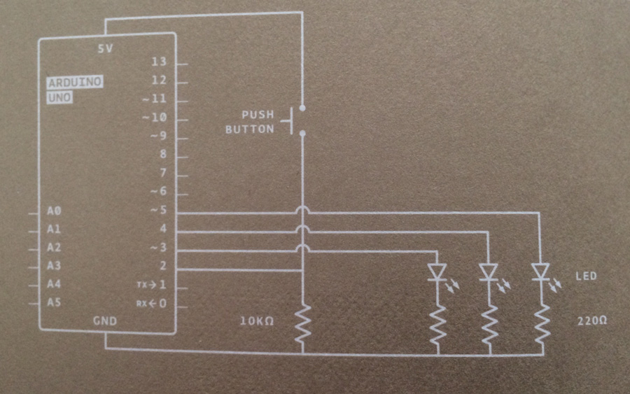
So everyone else knows where this is from enter image description here.
EDIT
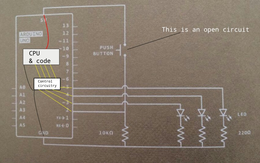
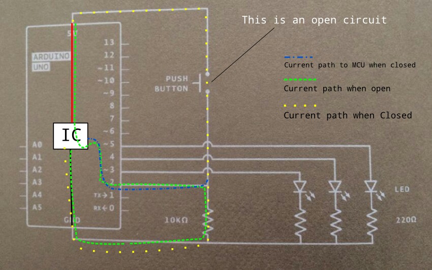
I have edited the image you gave to attempt to answer your question on 'wiring' :


The first image shows simply and crudely how the parts are basically connected or there relationship.
The second one shows how the current flows on the circuit, there is a key.
What you need to do is take the information from the link you give in the comment and apply logic to it, like if you used a logic probe and stuck it one end of the switch, the right side in that image, it would be high, if though you do so on the left it would be low. Hence no current flows in that circuit but there is current flow in the circuit looking at it.
What you have not examined is the code related to your project or the description of the project.
Looking at the code:
// Create a global variable to hold the
// state of the switch. This variable is persistent
// throughout the program. Whenever you refer to
// switchState, you’re talking about the number it holds
int switchstate = 0;

void setup() {
  // declare the LED pins as outputs
  pinMode(3, OUTPUT);
  pinMode(4, OUTPUT);
  pinMode(5, OUTPUT);

  // declare the switch pin as an input
  pinMode(2, INPUT);
}

void loop() {

  // read the value of the switch
  // digitalRead() checks to see if there is voltage
  // on the pin or not
  switchstate = digitalRead(2);

  // if the button is not pressed
  // turn on the green LED and off the red LEDs
  if (switchstate == LOW) {
    digitalWrite(3, HIGH); // turn the green LED on pin 3 on
    digitalWrite(4, LOW);  // turn the red LED on pin 4 off
    digitalWrite(5, LOW);  // turn the red LED on pin 5 off
  }
  // this else is part of the above if() statement.
  // if the switch is not LOW (the button is pressed)
  // turn off the green LED and blink alternatively the red LEDs
  else {
    digitalWrite(3, LOW);  // turn the green LED on pin 3 off
    digitalWrite(4, LOW);  // turn the red LED on pin 4 off
    digitalWrite(5, HIGH); // turn the red LED on pin 5 on
    // wait for a quarter second before changing the light
    delay(250);
    digitalWrite(4, HIGH); // turn the red LED on pin 4 on
    digitalWrite(5, LOW);  // turn the red LED on pin 5 off
    // wait for a quarter second before changing the light
    delay(250);
  }
}
From this we see that the default state of this code in the first if() statement is to turn on PIN3 and leave the rest off when the button is not pressed.
From Arduino:
A green LED will be ON, until you press a button. When the Arduino
gets a signal from the button, the green light will turn off and 2
other lights will start blinking.


he said that each pin on the board receives voltage after the battery is connected- not unless the code tells it to.