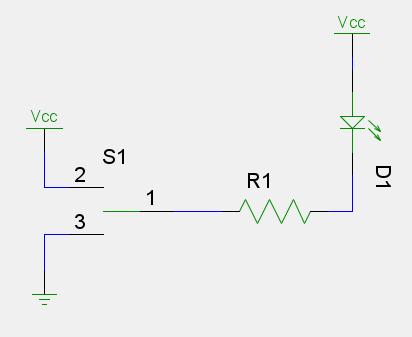
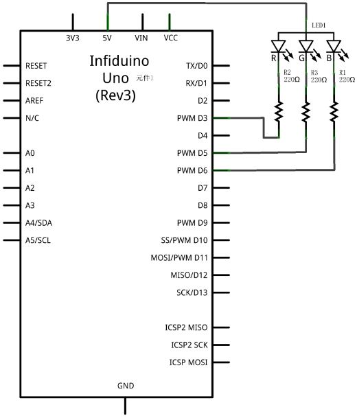
This is a common arrangement and is known as Common Anode, and the I/O pin is said to be sinking current.
To better understand what is happening here it's best to think of an I/O pin as a two-position switch:

When the I/O pin is HIGH point 1 is connected to point 2. When the I/O pin is LOW point 1 is connected to point 3.
So when HIGH the circuit is Vcc -> D1 -> R1 -> Vcc (or the other way around - I have done it that way because of the polarity of the LED), and no current can flow since it has nowhere that isn't at a lower potential than Vcc to flow to.
But when the I/O pin is LOW the circuit is now Vcc -> D1 -> R1 -> GND and so current can flow through it all to ground. As a result the LED now lights up.
One thing you may have noticed now is that the operation is backwards. Set the IO pin to LOW to turn the LED ON. That has the effect, as well, that PWM duty cycles are reversed. analogWrite(ledPin, 0) will be full brightness and analogWrite(ledPin, 255) will be off.


