Using two pins it is possible to drive 4 LEDs as long as you only want one of them on at a time. One LED will always be on - it's not possible to have a setting where there is no output selected.
Basically you are "decoding" a binary value output:
00 = LED 1 on, other three off
01 = LED 2 on, other three off
10 = LED 3 on, other three off
11 = LED 4 on, other three off
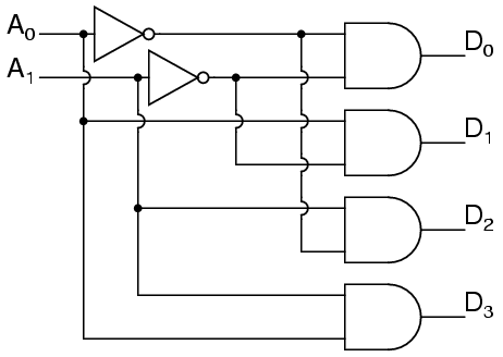
To do that you need to use (or construct) a 2-to-4 decoder.
Using logic gates it can be constructed like this:

If you can translate that into transistors then you'll end up with quite a lot of transistors. Most people would use a specific 2-to-4 decoder chip such as the 74HC139.
Shift registers usually require three pins, yes, though there are possible ways of working with two pins. You require two pins to provide the data and clock signals, and a third pin to latch the shifted data out to the outputs. However it is possible to use the first leading edge of the clock signal or a specially formatted data signal with a capacitor to create a pulse just before sending new data which can latch the old data. This requires careful consideration though regarding how fast you would be transmitting, etc, and is not really recommended.
A better solution if you are limited in pins and need to drive multiple LEDs is to use WS2812 "NeoPixel" LEDs which chain together and use a single wire protocol to send data to all the LEDs in the chain. You can support many LEDs (even hundreds) on a single IO pin, and they are full 24-bit RGB to boot.

