3

Explain this line in simple words.

TCCR0B=TCCR0B&0b11111000|0x01;

As the variuos arduinos have different chips. They also have different timers and different pins which use them.

Lately i want to rewrite a code(Arduino Uno) to make it work on a Arduino Micro.

I need to understand how this works in simple words. I normally write web based code(javascript,php...). Just lately i started writing in c++ or a "simplified" c++ in the arduino ide. It's not that hard. But some specific parameters are hard to understand for me. Shortcuts like the following.

TCCR0B=TCCR0B&0b11111000|0x01;

What does that?

TCCR0B

TCCR = Prefix for timers. Correct?

0 = Timer1 or 0 call it however you want.

B = What is A,B,C and sometimes D for? What does this?why in that code is the programmer using B and not A,C or D

TCCR0B= Timer 0 B is equal to:

TCCR0B& if Timer 0 B return True .. exists "&" ?

0b11111000 What is this? i already asked this and the answer was something like "clears the low-order 3 bits". Like i said, i'm not very familiar with c++, bits and other stuff regarding the arduino. I now less about the various chips and also about how they implemented the various parameters from arduino ide to work with those chips. I know that i have here 8 values that i can change from 0 to 1. What does those values change relative to the timer. Please think of me as a 6 year old.

|0x01; I got this... it sets the prescaler... 1,8,32.. some timers have differnet values... no problem. I need it at 1.

10
  • Related question: arduino.stackexchange.com/questions/14298/…
    – Nick Gammon
    Commented Aug 19, 2015 at 20:34
  • i already asked this and the answer was something like "clears the low-order 3 bits". Like i said, i'm not very familiar with c++, bits and other stuff regarding the arduino. - OK, you don't understand what "clear the low-order 3 bits" does. Then in another comment you say: This part is actually easy to understand for me as i work alot with coding language. also you can find easely online hex to decimal converters and so on. It isn't clear what you are asking. First you say you aren't familiar with C++ bits, then you say that's not what you are asking.
    – Nick Gammon
    Commented Aug 19, 2015 at 20:37
  • i needed a simple explaination about what those 3 bits and the other 7 bit change. I also didn't know what ABCD's that are appended to the TCCR0 are for. Those are different registers of 8 bit each. On probably all arduino to change the prescaler you only need the register B. the last 3 bits. those change the multipler. "TCCR0B=TCCR0B&0b11111000|0x01;" this line: timer 0 register B is reset and newly set to 1.Appropriate timers for the arduino micro vs the uno are pin 9,10,12 ... all use timer4 register b...and i need to change the last bits
    – cocco
    Commented Aug 19, 2015 at 20:53
  • 1
    Both Majenko and I posted an excerpt from the datasheet showing what each of the 8 bits in TCCR0B mean. If i don't know what i'm looking for i can't properly consult a 438 pages datasheet. - you look at the part for Timer 1 (or Timer 2 etc.) which is only a few pages. Then you look at the page describing TCCR0B. That describes each of those 8 bits. Each bit has a name (eg. WGMC13, CS10). Underneath the text in the datasheets explains what those bits do. The libraries on the Arduino are to help people write code without reading datasheets. If you want to go further, you have to read them.
    – Nick Gammon
    Commented Aug 19, 2015 at 21:12
  • 1
    i tought those... 3 bits change something different somewhere and that A B C & D is some sort of subset of the timer... now it's clear... ABCD is the "memory" of each timer that contains all the various settings... only the 3 bits in memory B change the prescaler. now that i know that also your answer is alot clearer.much clearer than the actual datasheet... they should rewrite the datasheet...
    – cocco
    Commented Aug 19, 2015 at 21:48

4 Answers 4

12

First I'll tackle what

TCCR0B=TCCR0B&0b11111000|0x01;

means from a pure programming perspective:

Let's break it down into parts:

TCCR0B = TCCR0B & 0b11111000 | 0x01;

TCCR0B is a register. It could be any variable really - it's just "a value" in this context. Just because it happens to control one of the timers is besides the point.

0b11111000 is a binary representation of a value. It's the same as the hexadecimal number 0xF8. F is 15. 15 in binary is 1111. 8 is 8 in both hexadecimal and decimal. 8 in binary is 1000. Put the two together and you have 11111000. Incidentally, in decimal that is 248.

0x01 is hexadecimal for 1 in decimal - it's also 1 in binary.

Between them are bitwise operators - & is a bitwise AND operation, and | is a bitwise OR operation. AND calculates which bits in a pair of binary numbers are both on, and OR calculates which bits in a pair of binary numbers are on in either of the numbers.

So take the first one first. Say the TCCR0B register contains the value 0x6F, which is 157 in decimal, or 01101111 in binary. The first operation is to AND that with 11111000:

01101111
11111000 AND
--------
01101000

You can see that the last three bits of the value have been cleared because they aren't 1 in both the left and right operands to the & operator.

Ok, so the next operation is to OR it with 0x01:

01101000
00000001 OR
--------
01101001

Effectively the two operands have been overlaid on each other and any bits that are set in either operand will be reflected in the result.

So finally the value is then stored in TCCR0B.

In summary that specific operation clears the lower three bits then sets the lowest bit of TCCR0B.

Now what that actually means with respect to what the TCCR0B register does can be gleaned from the datasheet for the chip. For instance, take the ATMega328P chip from the Arduino UNO board. Section 14.9.2 "TCCR0B – Timer/Counter Control Register B" of the datasheet describes that register in detail. The bit-wise overview looks like this:

enter image description here

Those bits all correspond 1:1 to the binary bits from above in the same order. So the first stage, clearing of the lowest three bits, sets CS02, CS01 and CS00 to 0. The second stage, ORing 0x01, then sets CS00 to 1.

The datasheet goes on to tell you what those mean:

  • Bits 2:0 – CS02:0: Clock Select

The three Clock Select bits select the clock source to be used by the Timer/Counter.

And a table to show the different meanings of the possible values:
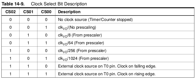
enter image description here

The value that has been masked and created for those three bits is, of course, 001, which in that table is "CLK I/O / (No prescaling)", which is the timer running at the frequency of the IO clock. If you were to set those bits to 010, you'd get "CLK I/O / 8 (From prescaler)". So your masking would change to:

TCCR0B = TCCR0B & 0b11111000 | 0x02;

Or more explicitly so you can see the bits easier:

TCCR0B = TCCR0B & 0b11111000 | 0b010;

As to what the "A" and "B" mean (TCCR0A and TCCR0B), there are two registers that are used to control the timer. They each serve a different purpose. TCCR0A has bits that control PWM, and TCCR0B has bits that control the timer itself.

Not to be confused with OCR0A and OCR0B which are two separate numeric values that are compared to the timer's counter value TCNT0 to provide two separate PWM outputs (OC0A as Uno pin D6, and OC0B as Uno pin D5) synchronised from the same timebase. (See sections 14.9.4 OCR0A – Output Compare Register A and 14.9.4 OCR0B – Output Compare Register B in the datasheet)

15
  • Actually i'm trying to get exactly not that as an answer.I need the part you skipped. This part is actually easy to understand for me as i work alot with coding language. also you can find easely online hex to decimal converters and so on. My question is what that line actually does in simple words. If i don't know what i'm looking for i can't properly consult a 438 pages datasheet. All i know is i need to set a timer to a prescaler of 1. Understanding whats the difference between TCCR1A,TCCR1B,TCCR1C or what those 8bit (0b11111000) represent.
    – cocco
    Commented Aug 19, 2015 at 12:41
  • Consider this.. i know nothing. i can code. "TCCR is just a value" you said. Why can't i just write: "Timer1 setPrescaler 1". Why do i need to write "Timer1b dosomething or set to 1"
    – cocco
    Commented Aug 19, 2015 at 12:41
  • If i knew where to look in the datasheet i would not be here. All i know is i need to change the prescaler of various pins of various timers of various chips of various boards. And now they are all different.
    – cocco
    Commented Aug 19, 2015 at 12:48
  • At the other side. if i would like an answer like this i would ask in stackoverflow and not here. It's an Arduino specific question.
    – cocco
    Commented Aug 19, 2015 at 12:49
  • 1
    @cocco On the other-other side, since this has nothing specific to do with Arduino, and is in fact about the ATMega chips that are on them, you would really ask this question on Electronics.SE. Most people who land here lack the basic programming skills to understand the bitwise operations, hence that is the answer given here - it is an answer for Arduino users, whereas you sound more like you may be looking for an EE answer.
    – Majenko
    Commented Aug 19, 2015 at 12:56
2

To add to Majenko's very thorough and excellent answer (which I can't yet upvote because I'm very newbie): Let's try to hone in on the line of code you need:

TCCR0B=TCCR0B&0b11111000|0x01;

On that particular Ardiuno, TCCR0B is the register that controls the rate of that particular timer. More specifically, the lowest 3 bits (the last in the 8-bit value) control the prescaler. The manufacturer labels those as CS02, CS01, and CS00. The combination of 1s and 0s in those three bits determines if the clock time is scaled or not, and by how much (or even if there is an external clock source). The reproduced table 14-9 will tell you how much the clock is "slowed down". This lets you create a 1Hz (1-second) timer, for example, rather than the 16Mhz (or whatever your particular board runs at) by scaling down how fast the timer "ticks". If you google "Arduino hardware timer calculator" or similar, you can find very helpful tools to help you set the clock frequency you want. Do that, since there are dangers to setting the wrong values, and your compiler may not catch what can be a serious error.

I only learned about hardware timers after exploring Arduino for a few years. Turns out they are very, very useful!

1

The answer, at high level, is: each bit (or group of bits) in a register is, in practice, like a knob that can configure certain parts of the HW. For each peripheral you want to control, you have to understand the block diagrams, the related knobs and in which registers those knobs are located. Sometimes there are multiple (almost) identical instances of a certain HW block and in the ATMega case these instances are often addressed with letters. So registers that have almost identical names, apart from A, B, C, are basically identical, but each of them will affect a separate instance of a certain peripheral. Depending on which pins or interrupt you want to use, you can choose the specific instance of a certain peripheral. You should check the ATMega328p programmer's manual (it's 2k pages, but it's easy to find the desired section.)

-1

I understand your question is not about c++ and bit manipulation.

It's not about "Arduino" neither, because your code line does only make sense for a certain avr microcontroller with a register named TCCR0B.

Sure, some arduinos are based on such microcontrollers and the c++ compiler used in the arduino toolchain allows access to those hardware registers via their names used in the datasheets.

Details however are beyond "Arduino" and should be looked up in the corresponding controller datasheet.

Your Answer

By clicking “Post Your Answer”, you agree to our terms of service and acknowledge you have read our privacy policy.

Not the answer you're looking for? Browse other questions tagged or ask your own question.