1

Where do I find the pins relative to timers of each individual Arduino microcontroller?

As I like Arduino's I already have various samples of them. The one I mostly use is the Uno and Micro for now... I'm planning to also get a Mega and others. Most simple things work on all devices, but if you start with complex code to fasten up things, every device is a little different. A problem I could not solve for days now is the relation between pins and timers.

I cannot find any information about the Arduino Micro. I also don't know exactly what the proper keywords are that I need to find the relation between timers and pins.

Example: A PWM driver multiplexing

As I for now just got some stuff from my local dealer I have no access to shift registers, PWM drivers and other proper integrated circuits.

So I used the Arduino as a PWM driver for 8 RGB or 24 (3*8) white LEDs. The code works on Arduino Uno. But as the Arduino Micro has no Timer2, TCCR2B, I cannot use the same code on the Arduino Micro.

Even if I understand the code (I wrote a lot in other languages...), some of the Atmel chip specific parameters are not clear.

This function sets the prescaler of the timer:

void setPwmFrequency(int pin, int divisor){

  byte mode;
  if(pin==5||pin==6||pin==9||pin==10){
    switch(divisor){
      case 1:mode=0x01;break;
      case 8:mode=0x02;break;
      case 64:mode=0x03;break;
      case 256:mode=0x04;break;
      case 1024:mode=0x05;break;
      default:return;
    }
    if(pin==5||pin==6){
      TCCR0B=TCCR0B&0b11111000|mode;
    } else{
      TCCR1B=TCCR1B&0b11111000|mode;
    }
  }else if(pin==3||pin==11){
    switch(divisor){
      case 1:mode=0x01;break;
      case 8:mode=0x02;break;
      case 32:mode=0x03;break;
      case 64:mode=0x04;break;
      case 128:mode=0x05;break;
      case 256:mode=0x06;break;
      case 1024:mode=0x7;break;
      default:return;
    }
    TCCR2B=TCCR2B&0b11111000|mode;
  }
}

First of all, I probably don't even need this function as soon I know what frequency I want, and so I probably need only two lines to set my three (RGB) pins.

//Arduino Uno timer setup for pin 9, 10, and 11
TCCR1B=TCCR1B&0b11111000|0x01; // Pin 9,10
TCCR2B=TCCR2B&0b11111000|0x01; // Pin 11
  1. Correct, I need to set TCCR1B only one time?

  2. What does the 0b11111000 refer to?

In the setup function there is also this line:

TIMSK2 = 1<<TOIE2;
  1. What does this do?

While the above three questions are not so important until it works, I need to understand how I can convert those timers to work with Arduino Micro, but also later with other Arduino boards.


On Arduino Micro

There is no timer 2

Do pin 9, 10, and 12 have the same timer?

??????=??????&0b11111000|0x01;

Also if I understand correctly the Arduino Micro has:

  1. A higher PWM range 1024 vs 255 (UNO)??
  2. A much higher frequency available in on Timer4 only for pin 13

So is there somewhere a table describing the differences between all Arduino timers?

Full working (on Arduino Uno) code.

unsigned char Prescaler=0;
unsigned char CurrentLED=0;
unsigned char LEDValues[8][3];
unsigned char ports[8]={
  0b00000100,
  0b00001000,
  0b00010000,
  0b00100000,
  0b01000000,
  0b10000000,
  0b00000001,
  0b00010000
};//PINS 2,3,4,5,6,7,8,12

#define PrescalerOverflowValue 4

ISR(TIMER2_OVF_vect){
  if(Prescaler<PrescalerOverflowValue){
    Prescaler++;
  }else {
    Prescaler=0;
    Multiplex();
  }
}

void Multiplex(void){
  PORTD&=0b00000011;
  PORTB&=0b11101110;
  analogWrite(9,255-LEDValues[CurrentLED][0]);
  analogWrite(10,255-LEDValues[CurrentLED][1]);
  analogWrite(11,255-LEDValues[CurrentLED][2]);
  CurrentLED<6?(PORTD|=ports[CurrentLED]):(PORTB|=ports[CurrentLED]);
  CurrentLED++;
  if(CurrentLED>7)CurrentLED=0;
}
void setPwmFrequency(int pin, int divisor){
  byte mode;
  if(pin==5||pin==6||pin==9||pin==10){
    switch(divisor){
      case 1:mode=0x01;break;
      case 8:mode=0x02;break;
      case 64:mode=0x03;break;
      case 256:mode=0x04;break;
      case 1024:mode=0x05;break;
      default:return;
    }
    if(pin==5||pin==6){
      TCCR0B=TCCR0B&0b11111000|mode;
    }else{
      TCCR1B=TCCR1B&0b11111000|mode;
    }
  }else if(pin==3||pin==11){
    switch(divisor){
      case 1:mode=0x01;break;
      case 8:mode=0x02;break;
      case 32:mode=0x03;break;
      case 64:mode=0x04;break;
      case 128:mode=0x05;break;
      case 256:mode=0x06;break;
      case 1024:mode=0x7;break;
      default:return;
    }
    TCCR2B=TCCR2B&0b11111000|mode;
  }
}

void setup(void){

  pinMode(2,OUTPUT);//1
  pinMode(3,OUTPUT);//2
  pinMode(4,OUTPUT);//3
  pinMode(5,OUTPUT);//4
  pinMode(6,OUTPUT);//5
  pinMode(7,OUTPUT);//6
  pinMode(8,OUTPUT);//7
  pinMode(12,OUTPUT);//8
  pinMode(9,OUTPUT);//red
  pinMode(10,OUTPUT);//green
  pinMode(11,OUTPUT);//blue
  setPwmFrequency(9,8);
  setPwmFrequency(10,8);
  setPwmFrequency(11,8);
  TIMSK2=1<<TOIE2;
}

void loop(void){
  for(int i=0;i<8;i++){
    //LEDValues[i][0]; // Red
    //LEDValues[i][1]; // Green
    //LEDValues[i][2]; // Blue
  }
}

2 Answers 2

7

I cannot find any information about the arduino micro. I also don't know exactly what the proper keywords are that i need to find the relation between timers and pins.

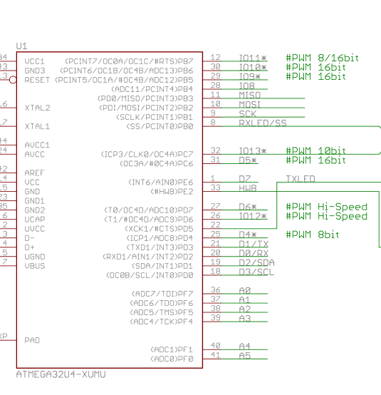
Now we know the processor, the datasheet tells you about the timers, and the schematic tells you which ATmega32U4 pins are connected to which pins on the Micro board.


But as the Arduino Micro has no Timer2 TCCR2B i cannot use the same code on the Arduino micro.

True. But it has Timer 1, Timer 3 and Timer 4. You just need to adjust the registers a bit.


Correct, I need to set TCCR1B only one time?

Yes you can do that. Personally I normally stop the timer and then set the parameters in case setting them when it is running has a different effect. eg

TCCR1A = 0;  // stop timer 1
TCCR1B = 0;
TCCR1C = 0;

   TCCR1B=TCCR1B&0b11111000|0x01; //pin 9,10

What do the 0b1111000 refer to?

In this case the first part TCCR1B & 0b11111000 clears the low-order 3 bits (the rest are ANDed in with 1 so they stay the same as before).

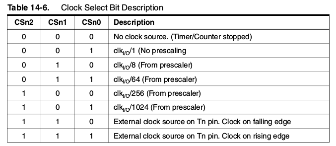
Then it sets the lower-order bit. In this particular case you are setting up a prescaler of 1 times the clock rate.

TCCR1b

Clock pre-scalers for timer 1


   TIMSK2=1<<TOIE2;

what does this ?

TIMSK2 is a timer register.

TIMSK2

By shifting 1 left "TOIE2" bits it sets that bit (ie., TOIE2 in TIMSK2).

In other words, it enables the overflow interrupt for Timer 2.


On Arduino Micro There is no timer 2 Pin 9,10,12 have the same timer ?

Look at the reference schematic. Yes it looks like it.

Micro schematic part

As you can see from that pin 30 (on the chip) is labelled OC4B which means it is the "output compare timer 4: B output". That pin has the net name "IO10*" which I presume means it is connected to board pin 10 (pin 30 on the chip).


Also if I understand correctly the Arduino micro has:

  1. a higher PWM range 1024 vs 255 (UNO)??
  2. a much higher frequency available in on timer4 only for pin 13

No, the Uno has Timer 1 which is 16 bits (up to 65536). The Micro has Timer 4 which is 10 bits and therefore can count up to 1024.

Anyway, the frequency is a function of the clock speed. On either chip, by using a prescaler of 1, and counting up to 1, you can get an 8 MHz frequency (one up, one down from 16 MHz).

The higher number of bits in the timer, the finer the resolution - that is you can adjust the frequency in finer steps, and you can adjust the PWM duty cycle in finer steps.

However with Timer 4 on the Micro you can, apparently, clock it with 6 times the clock rate (96 MHz) which is used for the USB part of the chip. Setting appropriate bits (I haven't done this personally) you could get that higher frequency.

You can apparently get 96 MHz, 64 MHz or 48 MHz clock frequencies on Timer 4 (as well as the normal ones).


Added in response to comments

Pin 12 on the chip has 2 timers, OC0A & OC1C??

Yes, from the datasheet:

The Output Compare unit 1C and Output Compare unit 2 shares the PB7 port pin for output. The outputs of the Output Compare units (OC1C and OC0A) overrides the normal PORTB7 Register when one of them is enabled (i.e., when COMnx1:0 is not equal to zero). When both OC1C and OC0A are enabled at the same time, the modulator is automatically enabled.


What timer do i need to use for let's say pin 9,10,12 on arduino micro?

Looks like Timer 4.


in arduino ide i can only write analogWrite(255)

That is changing the PWM duty cycle for the timers configured in their default way.

Have a look in wiring.c:

// timers 1 and 2 are used for phase-correct hardware pwm
// this is better for motors as it ensures an even waveform
// note, however, that fast pwm mode can achieve a frequency of up
// 8 MHz (with a 16 MHz clock) at 50% duty cycle

analogWrite changes the duty cycle, not the frequency.


You can apparently get 96 MHz... so at the end arduino micro can go faster on timer 4

I'm not sure what you mean by "go faster" here.


but I actually did not solve the problem. I hope you give me a hint to how to make it work.

It isn't clear really what you want to happen.

  • What devices are you driving?
  • Why do you need high frequencies?
  • What is the underlying problem?

Reference

  • Timers and counters - mainly about the Atmega328P, however a lot of it applies to the other chips as well.
1
0

You can check pins_arduino.h file as well.

// ATMEL ATMEGA32U4 / ARDUINO LEONARDO
//
// D0               PD2                 RXD1/INT2
// D1               PD3                 TXD1/INT3
// D2               PD1     SDA         SDA/INT1
// D3#              PD0     PWM8/SCL    OC0B/SCL/INT0
// D4       A6      PD4                 ADC8
// D5#              PC6     ???         OC3A/#OC4A
// D6#      A7      PD7     FastPWM     #OC4D/ADC10
// D7               PE6                 INT6/AIN0
//
// D8       A8      PB4                 ADC11/PCINT4
// D9#      A9      PB5     PWM16       OC1A/#OC4B/ADC12/PCINT5
// D10#     A10     PB6     PWM16       OC1B/0c4B/ADC13/PCINT6
// D11#             PB7     PWM8/16     0C0A/OC1C/#RTS/PCINT7
// D12      A11     PD6                 T1/#OC4D/ADC9
// D13#             PC7     PWM10       CLK0/OC4A
//
// A0       D18     PF7                 ADC7
// A1       D19     PF6                 ADC6
// A2       D20     PF5                 ADC5
// A3       D21     PF4                 ADC4
// A4       D22     PF1                 ADC1
// A5       D23     PF0                 ADC0
//
// New pins D14..D17 to map SPI port to digital pins
//
// MISO     D14     PB3                 MISO,PCINT3
// SCK      D15     PB1                 SCK,PCINT1
// MOSI     D16     PB2                 MOSI,PCINT2
// SS       D17     PB0                 RXLED,SS/PCINT0
//
// TXLED    D30     PD5                 XCK1
// RXLED    D17     PB0
// HWB              PE2                 HWB

There is an array inside the same file with name digital_pin_to_timer_PGM that list the timers also.

const uint8_t PROGMEM digital_pin_to_timer_PGM[] = {
    NOT_ON_TIMER,
    NOT_ON_TIMER,
    NOT_ON_TIMER,
    TIMER0B,        /* 3 */
    NOT_ON_TIMER,
    TIMER4A,        /* 5 */
    TIMER4D,        /* 6 */
    NOT_ON_TIMER,

    NOT_ON_TIMER,
    TIMER1A,        /* 9 */
    TIMER1B,        /* 10 */
    TIMER0A,        /* 11 */

    NOT_ON_TIMER,
    TIMER4A,        /* 13 */

    NOT_ON_TIMER,
    NOT_ON_TIMER,
    NOT_ON_TIMER,
    NOT_ON_TIMER,
    NOT_ON_TIMER,
    NOT_ON_TIMER,

    NOT_ON_TIMER,
    NOT_ON_TIMER,
    NOT_ON_TIMER,
    NOT_ON_TIMER,
    NOT_ON_TIMER,
    NOT_ON_TIMER,
    NOT_ON_TIMER,
    NOT_ON_TIMER,
    NOT_ON_TIMER,
    NOT_ON_TIMER,
    NOT_ON_TIMER,
};

Your Answer

By clicking “Post Your Answer”, you agree to our terms of service and acknowledge you have read our privacy policy.

Not the answer you're looking for? Browse other questions tagged or ask your own question.