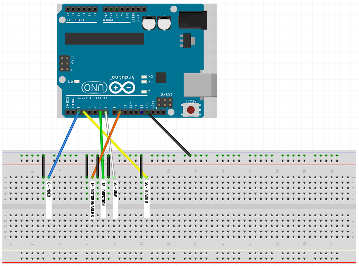
After researching a solution to a problem I want to solve, I'm hoping the third time posting is a charm. :)
I'd like to use an Arduino to control a vintage floppy disk drive. I'm looking to use it as a testing platform to first make sure that various basic functions (Motor spinning, stepping in, stepping out,going back to track 0) all work, and as a bonus I'd like to be able to test writing and reading data. Hopefully by using the Arduino I have more control over the functions instead of attaching it to a system and trying "dir" or "copy" and hoping things are happening correctly.
In my research, I found an article from 2014 (Controlling Floppy Disk Drive with Arduino and another in 2017 Simple reading and writing on Floppy Disk. The first article never was able to get the basic functionality working, the second article (Based on the first one) seemed to skip over the basic functions and go straight to reading/writing.
The first poster's issue was -
I am expecting the Index to pulse when the disk motor makes a rotation, and for Track 0 to change when I am at the outside of the disk, but they are both always LOW. Am I missing something?
They don't specifically say it, but they never confirmed the stepping was working.
I'm using the code directly from the first article with the suggested tweak by @geometrikal as -
//https://arduino.stackexchange.com/questions/3702/controlling-floppy-disk-drive-with-arduino
//
//constants
static const int IN = LOW;
static const int OUT = HIGH;
static const int pulseDelayTime = 6;

//pins
int indexPin = 2; //8 on the drive INDEX
int track0Pin = 3; //26 on the drive. TRACK 0
int dirPin = 6; //18 on the drive. DIRECTION
int stepPin = 7; //20 on the drive. STEP
int motorEnableBPin = 9; //16 on the drive. MOTOR ENABLE B

unsigned long motorSpinTime = 1000UL; //in ms


void setup() {

  //initial delay
  delay(3000);

  //setup serial monitor
  Serial.begin(9600);

  //setup pins.
  pinMode(dirPin, OUTPUT);
  pinMode(stepPin, OUTPUT);
  pinMode(motorEnableBPin, OUTPUT);
  //pinMode(indexPin, INPUT); - Original code from @jeffctown
  //pinMode(track0Pin, INPUT); - Original code from @jeffctown
  //Code suggested by @geometrikal in https://arduino.stackexchange.com/a/3706/106869
  pinMode(indexPin, INPUT_PULLUP);
  pinMode(track0Pin, INPUT_PULLUP);
  //turn the motor off initially
  digitalWrite(motorEnableBPin, HIGH);

  //print state here.
  printState("Setup done.");

  //spin the disk some.
  printState("Begin to spin motor");
  spinMotorForThisManyMs(motorSpinTime);
  spinMotorForThisManyMs(motorSpinTime);
  printState("Done spinning motor");

  //step read/write head all the way in.
  stepAllTheWayIn();

  //spin the disk some more.
  printState("Begin to spin motor");
  spinMotorForThisManyMs(motorSpinTime);
  spinMotorForThisManyMs(motorSpinTime);
  printState("Done spinning motor");

  //step read/write head all the way out.
  stepAllTheWayOut();

  //spin the disk even more.
  printState("Begin to spin motor");
  spinMotorForThisManyMs(motorSpinTime);
  spinMotorForThisManyMs(motorSpinTime);
  printState("Done spinning motor");

  //never completes.
  waitForIndex();
}

void loop() {
}

//spins the disk motor for a number of ms and prints the state
void spinMotorForThisManyMs(unsigned long msToSpin) {

  //start spinning
  digitalWrite(motorEnableBPin,LOW);

  //delay.. keep printing the state
  unsigned long maxTimeMs = millis() + msToSpin;
  while(millis() < maxTimeMs ) {
    printState("Spinning");
  }

  //stop spinning
  digitalWrite(motorEnableBPin,HIGH);
}


//step the read/write head all the way to the center
void stepAllTheWayIn() {
  for(int i=0;i<100;i++) {
    printState("Stepping In");
    stepInALittle();
  }
}

//step the read/write head all the way to the outside
void stepAllTheWayOut() {
  for(int i=0;i<100;i++) {
    printState("Stepping Out");
    stepOutALittle();
  }
}

//print the state of the index and track
void printState(const char* charPrint) {
  Serial.print(" Index:");
  Serial.print(digitalRead(indexPin));
  Serial.print(" Track:");
  Serial.print(digitalRead(track0Pin));
  Serial.print(" ");
  Serial.println(charPrint);
}

//move the head towards the outside a little
void stepOutALittle() {
  digitalWrite(dirPin,HIGH);
  stepPulse();
}

//move the head towards the center a little
void stepInALittle() {
  digitalWrite(dirPin,LOW);
  stepPulse();
}

//pulse the step pin
void stepPulse() {
  digitalWrite(stepPin,LOW);
  delay(pulseDelayTime);
  digitalWrite(stepPin,HIGH);
}

//waits for the index to trigger. this never gets completed.
void waitForIndex() {

  printState("beginning to wait for index pin to pulse");

  //start spinning
  digitalWrite(motorEnableBPin,LOW);

  //wait for pulse
  while(digitalRead(indexPin));
  //wait for end of pulse 0
  while(!digitalRead(indexPin));

  printState("end of waiting for index pin to pulse");

  //stop spinning
  digitalWrite(motorEnableBPin,HIGH);
}
And the same exact pinouts from the first article too.
For track stepping, it first sets-
pinMode(stepPin, OUTPUT);
and later on does -
digitalWrite(dirPin,HIGH);
// Step routine
digitalWrite(stepPin,LOW);
delay(pulseDelayTime);
digitalWrite(stepPin,HIGH);
It should step out, and by setting dirPin to LOW it should step in. Neither one of these functions seem to be happening with my setup. I've checked the wiring 1/2 a dozen times and reviewed the code with no luck.
The second article (Based on the first) was concentrating more on read/write, which means they may not have paid attention to stepping.(Not to mention they weren't able to write).
I checked the pinning, and the code, and there isn't anything I can understand that might be causing the issues.
Wondered if anyone understands why what's expected isn't happening or has found or created their own code to be able to put a drive through some of its paces.
Thanks, Tuc


Wondered if anyone has found a solution to this issue.that is a chat suitable for a forum, but this site is not a forum ... a question about the problem is required here