3

I need help getting my MPU 6050 to actually give me data. As of right now, my program is only reading 0s from the gyroscope and when I move it, the values all go to -1 and the program just stops until I close and reopen the serial monitor. I know this question has been asked multiple times before, but I've already looked at each of those questions and tried all of the fixes listed there, but not a single one has worked. The I2C scanner does find the sensor at 0x68, but that's only thing that works. These are all brand new boards that I got a couple days ago.

I've tried every library and every example sketch I could find. I've switched to 2 new boards. I've even tried looking at the datasheet for the MPU 6050 and reading/writing the registers directly and still I'm getting no results. The serial monitor either stays blank, shows only 0s or -1s, or just gives me garbage values that change randomly. Please help me.

I've wired the sensor like this (I'm currently on an Arduino Uno):

VCC ==> 5V
GND ==> GND
SCL ==> A5
SDA ==> A4
AD0 ==> digital 13 (set to LOW)

And the code I'm using is this:

#include <Wire.h>

const int addressPin = 13;

int gyroX, gyroY, gyroZ;

void setup() {
  Wire.begin();
  Serial.begin(9600);

  //designating pins as I/O
  pinMode(addressPin, OUTPUT);

  //setting IMU address to 0x68 (LOW)
  digitalWrite(addressPin, LOW);

  initializeSensor();
}

void loop() {
  readGyro();

  Serial.print(gyroX);
  Serial.print("    ");
  Serial.print(gyroY);
  Serial.print("    ");
  Serial.println(gyroZ);
}

void initializeSensor() {
  //performing full device reset, disables temperature sensor, disables SLEEP mode
  Wire.beginTransmission(0x68);

  Wire.write(0x6B);
  Wire.write(0b10001000);

  Wire.endTransmission();

  //writing to gyro config register
  Wire.beginTransmission(0x68);

  Wire.write(0x1B);
  Wire.write(0b00001000);

  Wire.endTransmission();
}

void readGyro() {
  //requesting data from gyro data registers
  Wire.beginTransmission(0x68);

  Wire.write(0x43);
  
  Wire.endTransmission();

  Wire.requestFrom(0x68, 6);
  
  gyroX = Wire.read()<<8|Wire.read();
  gyroY = Wire.read()<<8|Wire.read();
  gyroZ = Wire.read()<<8|Wire.read();
}

P.S. I few weeks ago I posted a question about I2C devices and in it, I said I had managed to successfully read data from the sensor, but I found out later those were garbage numbers. :(

1
  • 1
    It would be good to link to the questions on which you tried all solutions so people know exactly what not to repeat. If you can, inspect the signals with a scope. One potential difference between the I2C scanner and libraries is the requested clock rate.
    – timemage
    Commented Jul 22, 2021 at 20:22

3 Answers 3

3

From the MPU-6000/MPU-6050 Register Map and Descriptions:

  • Section 4.28, Register 107 – Power Management 1 PWR_MGMT_1, pages 40 to 41:

    Note:
    When using SPI interface, user should use DEVICE_RESET (register 107) as well as SIGNAL_PATH_RESET (register 104) to ensure the reset is performed properly. The sequence used should be:

    1. Set DEVICE_RESET = 1 (register PWR_MGMT_1)
    2. Wait 100ms
    3. Set GYRO_RESET = ACCEL_RESET = TEMP_RESET = 1 (register SIGNAL_PATH_RESET)
    4. Wait 100ms
  • Section 4.26, Register 104 – Signal Path Reset SIGNAL_PATH_RESET, page 37:

    Note: This register does not clear the sensor registers. The reset initializes the serial interface as well.

  • Section 3, Register Map, page 8:

    The reset value is 0x00 for all registers other than the registers below.

    • Register 107: 0x40.
    • Register 117: 0x68.

This means that the PWR_MGMT_1 register defaults to sleep mode after a reset so it needs to be rewritten to disable sleep mode after commanding a reset.

void initializeSensor()
{
  //
  // Perfrom full reset as per MPU-6000/MPU-6050 Register Map and Descriptions, Section 4.28, pages 40 to 41.
  //

  // performing full device reset, disables temperature sensor, disables SLEEP mode
  Wire.beginTransmission(0x68);  // Device address.
  Wire.write(0x6B);              // PWR_MGMT_1 register.
  Wire.write(0b10001000);        // DEVICE_RESET, TEMP_DIS.
  Wire.endTransmission();
  delay(100);                    // Wait for reset to complete.

  Wire.beginTransmission(0x68);  // Device address.
  Wire.write(0x68);              // SIGNAL_PATH_RESET register.
  Wire.write(0b00000111);        // GYRO_RESET, ACCEL_RESET, TEMP_RESET.
  Wire.endTransmission();
  delay(100);                    // Wait for reset to complete.

  // Disable SLEEP mode because the reset re-enables it. Section 3, PWR_MGMT_1 register, page 8.
  Wire.beginTransmission(IMUAddress);   // Device address.
  Wire.write(0x6B);                     // PWR_MGMT_1 register.
  Wire.write(0b00001000);               // SLEEP = 0, TEMP_DIS = 1.
  Wire.endTransmission();
}

In the following code I've:

  1. Modified readGyro() to implement 3 states (Request, Wait, and Read) and return true when 6 bytes have been read from the MPU-6050.

  2. Added Blink Without Delay to loop() to see whether the MCU freezes which requires changing the ADO pin from pin 13 (the built-in led) to another pin, i.e. pin 12.

  3. Added several Serial.print() statements for debugging to see where things go wrong.

  4. Tweaked the code in response to comments.

#include <Wire.h>

const byte IMUAddress = 0x68;   // Added for readability and maintainability.
const byte addressPin = 12;     // Changed from 13 to 12 because 13 is built-in LED.

int gyroX, gyroY, gyroZ;

void setup()
{
  Wire.begin();
  Serial.begin(115200);
  Serial.println(F("\n\nMPU-6050 Test\n"));

  // Designating pins as I/O.
  pinMode(addressPin, OUTPUT);
  pinMode(LED_BUILTIN, OUTPUT);  // Added LED for heartbeat signal.

  // Setting IMU address to 0x68 (LOW).
  digitalWrite(addressPin, IMUAddress & 1);  // Added bit mask of bit 0.

  initializeSensor();
}

void loop()
{
  //
  // TASK 1: Blink without delay to indicate that MCU hasn't frozen.
  //
  const unsigned int INTERVAL = 250;
  unsigned long current_timestamp = millis();
  static unsigned long previous_timestamp = current_timestamp;
  static bool led_state = false;
  if (current_timestamp - previous_timestamp >= INTERVAL)
  {
    led_state = !led_state;
    digitalWrite(LED_BUILTIN, led_state);
    previous_timestamp += INTERVAL;
  }

  //
  // TASK 2: Read gyro.
  //
  if (readGyro())
  {
    Serial.print(gyroX);
    Serial.print(F("    "));
    Serial.print(gyroY);
    Serial.print(F("    "));
    Serial.println(gyroZ);
  }
}

void initializeSensor()
{
  //
  // Perform full reset as per MPU-6000/MPU-6050 Register Map and Descriptions, Section 4.28, pages 40 to 41.
  //

  Serial.print(F("Performing full reset of MPU-6050..."));

  Wire.beginTransmission(IMUAddress);   // Device address.
  Wire.write(0x6B);                     // PWR_MGMT_1 register.
  Wire.write(0b10001000);               // DEVICE_RESET, TEMP_DIS.
  Wire.endTransmission();
  delay(100);                           // Wait for reset to complete.

  Wire.beginTransmission(IMUAddress);   // Device address.
  Wire.write(0x68);                     // SIGNAL_PATH_RESET register.
  Wire.write(0b00000111);               // GYRO_RESET, ACCEL_RESET, TEMP_RESET.
  Wire.endTransmission();
  delay(100);                           // Wait for reset to complete.

  Serial.println(F(" Done."));

  // Disable SLEEP mode because the reset re-enables it. Section 3, PWR_MGMT_1 register, page 8.
  Serial.print(F("Disabling sleep mode of MPU-6050..."));
  Wire.beginTransmission(IMUAddress);   // Device address.
  Wire.write(0x6B);                     // PWR_MGMT_1 register.
  Wire.write(0b00001000);               // SLEEP = 0, TEMP_DIS = 1.
  Wire.endTransmission();
  Serial.println(F(" Done."));

  //
  // Writing to gyro config register.
  //
  Serial.print(F("Configuring gyro of MPU-6050..."));
  Wire.beginTransmission(IMUAddress);   // Device address.
  Wire.write(0x1B);                     // GYRO_CONFIG register.
  Wire.write(0b00001000);               // +/-500 deg/s.
  Wire.endTransmission();
  Serial.println(F(" Done."));
}

typedef enum State
{
  Request,
  Wait,
  Read
};

bool readGyro()
{
  static State state = State::Request;

  switch (state)
  {
    case State::Request:
      // Request data from gyro data registers.
      Serial.print(F("Requesting data from gyro..."));
      Wire.beginTransmission(IMUAddress);   // Device address.
      Wire.write(0x43);                     // GYRO_XOUT_H register.
      Wire.endTransmission(false);          // Restart connection, i.e. keep alive.
      Wire.requestFrom(IMUAddress, 6);      // GYRO_XOUT_H, GYRO_XOUT_L, GYRO_YOUT_H, GYRO_YOUT_L, GYRO_ZOUT_H, GYRO_ZOUT_L.
      Serial.println(F(" Done."));
      state = State::Wait;
      Serial.print(F("Waiting for data from gyro..."));
      break;

    case State::Wait:
      // Wait for data to arrive into buffer.
      if(Wire.available() < 6)
      {
        //Serial.print(F("."));
        Serial.print(F(" "));
        Serial.print(Wire.available());  // Added to show bytes received.
      }
      else
      {
        Serial.print(F(" "));
        Serial.print(Wire.available());  // Added to show bytes received.
        Serial.println(F(" Done."));
        state = State::Read;
      }
      break;

    case State::Read:
      // Read data from gyro registers.
      Serial.print(F("Reading gyro data..."));
      gyroX = Wire.read() << 8 | Wire.read();
      gyroY = Wire.read() << 8 | Wire.read();
      gyroZ = Wire.read() << 8 | Wire.read();
      Serial.println(F(" Done."));
      state = State::Request;
      return true;  // Indicate data was received.
      break;
  }

  return false;  // Indicate no data received yet.
}

Update based upon RowanP's answer

While concentrating on the software issues I missed a crucial piece of information from the other datasheet (MPU-6000/MPU-6050 Product Specification), i.e. the electrical characteristics in Sections 6.3 and 6.4 on pages 14 and 15 showing a Vdd range of 2.375 V to 3.46 V:

Electrical Characteristics of MPU-6050 Vdd power supply of MPU-6050

6.4 Electrical Specifications, Continued Digital inputs and outputs of MPU-6050
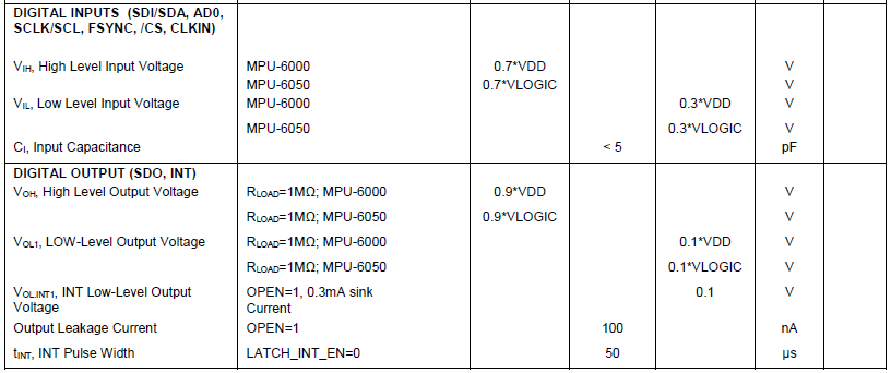
This will require level shifters on the signals between the 3.3 V MPU-6050 and the 5 V Arduino.

7
  • Thanks for the help! I've looked through the checklist that RowanP gave me and fixed anything that I thought might have been wrong, including switching to the 3.3V pin for power on the Uno. I've also used your code and it appears to still only give 0s, but when I rotate the sensor about the y-axis the code gets stuck in the State :: Wait case and only prints periods (but the heartbeat light doesn't stop). Do you have any idea why?
    – Tobias Guo
    Commented Jul 23, 2021 at 16:06
  • @TobiasGuo, as others have said, the chip could be damaged by a 5 V supply. While 5 V is within the absolute maximum rating of 6 V, it's outside the recommended operating voltage. Do you have level shifters on SCL, SDA and ADO? Try replacing the period print with Serial.println(Wire.available()); to see how many bytes it manages to read.
    – tim
    Commented Jul 24, 2021 at 11:25
  • @TobiasGuo, you could also print and test the return value of each Wire.endTransmission().
    – tim
    Commented Jul 24, 2021 at 11:34
  • @TobiasGuo, did you get it working? I noticed from your question about accelerometer values that you changed the code, i.e. disabled the SLEEP mode without performing a reset because the reset re-enables SLEEP mode (Section 3, PWR_MGMT_1 register, page 8), and used keep-alive with Wire.endTransmission(false) before requesting data.
    – tim
    Commented Jul 24, 2021 at 17:09
  • 1
    Thanks! That seems to have fixed the problem! I also switched to using the I2Cdev library and that helped streamline the process of communicating with the sensors, but now my MPUs are actually giving me the correct output!
    – Tobias Guo
    Commented Jul 26, 2021 at 17:21
3

A while ago while figuring out I2C difficulties of my own I did some research and listed out all the failure modes and test techniques I could think of regarding I2C. See I2C protocol doesn't work properly. I routinely go through the list now to tick off the things I need to check to get a new I2C connection working, usually it's something simple (fingers crossed). Do you have access to an oscilloscpe?

(Edit) This old post seems to describe a similar problem (only getting zeros) MPU6050 doesn't work. The consensus there was that the 3.3V MPU6050 had been connected to a 5V UNO, frying the MPU6050 chip. That sounds very like your situation.

4
  • Thanks for linking that checklist. I will run through that to see if I have missed anything or if there is anything else I can do to fix it. I was under the impression that the VCC pin on the MPU 6050 was designed to be able to handle a 5V power supply, but maybe I was wrong. I will definitely try switching to a 3.3V power supply!
    – Tobias Guo
    Commented Jul 23, 2021 at 14:17
  • 1
    What module are you using? I'm using the DFRobots 6DOF module (wiki.dfrobot.com/6_DOF_Sensor-MPU6050__SKU_SEN0142_) and it works fine with a 5V supply. You might also try taking a look at this (fpaynter.com/2019/10/basic-arduino-mpu6050-gy-521-test) and related articles about the MP6050 on my website (fpaynter.com)
    – starship15
    Commented Jul 27, 2021 at 19:40
  • I went back and checked my most recent use of an MPU6050 module, and notwithstanding the link I posted in my answer, I agree with @user3765883, the modules I've had are 5V tolerant as well. I don't have a schematic, but looking at the module closely there is a power regulator onboard marked 4A20. Depending on the specific module you're using I think the previous link about the MPU6050 chip being 3.3 V may be a red herring!
    – RowanP
    Commented Jul 27, 2021 at 22:37
  • OK, so there is evidence of at least two different types of modules in circulation. One with a 5 to 3.3 V power regulator and one without. See forum.arduino.cc/t/mpu6050-eagle-files-out-of-date/633197
    – RowanP
    Commented Jul 27, 2021 at 22:50
2

I used 5 V from my Arduino to power the MPU6050, and it was fine. Check out: https://www.instructables.com/How-to-Make-a-Robot-Car-Drive-Straight-and-Turn-Ex/, which has very similar code.

Also, I typically avoid pin 13, since it performs some special additional function, unlike pin 2 to 12.

Your Answer

By clicking “Post Your Answer”, you agree to our terms of service and acknowledge you have read our privacy policy.

Not the answer you're looking for? Browse other questions tagged or ask your own question.